TECHNICAL |
PTF 9-16
|
|
|
[ Technical ] 9
|
Articles:9.1. ALIGNMENT SCHEDULE FOR THE PROPULSION
MACHINERY |
Figures:9.2.2. Docking plan9.4 Door and locker key plan |
During the construction of the hull certain fixed datum points ore obtained and are carefully marked to facilitate future maintenance.
These datum points are marked with triangular shaped metal plates and from these points the necessary measurements can be taken.
When checking the propeller shaft, stern tube and propeller bracket alignment, a wire is held taut between the triangular plate mounted on the bulkhead frame 49 and a point subtended below the datum point on the outboard side of the transom as stated in article 9.1.2.
The initial datum point of the alignment of the propulsion machinery is the forward edge of frame 55, see figure.
By means of a wood block fixed to bulkhead frame 49, the distance of 2100 mm -- 6' 1043/64"--from the frame is obtained.
The forward point for the alignment is found 1087 mm -- 3' 6 25132" above base line and 1200 mm -- 3' 11'5/61" -- from the centre line of the boat. The point is marked with a bronze triangle on the wood block
The after point for the alignment wire is positioned 613,3 mm -- 2' 1/8" below base line and 1200 mm -- 3' 11 15/64" from centre line of the boat. A bronze plate with groove for a plumb line is attached to the transom. The point for the alignment wire is found 1200 mm -- 3' 11' 5/64" down on the plumb line from the lower angle of the triangle. The accurate distance from frame 55 which should be 5900 mm -- 19' 4 9/32" is compensated for when the bronze triangle is mounted.
When the boot is built the alignment tolerances in bracket and stern tube are set to 0.016". This alignment is done while the boat is still laying on the building slip. These tolerances are probably of no value when the boat is later put into a slipway. In this respect we consider that alignment tolerances for brackets and stern tubes, if they are checked for any reason, ought to be a matter of experience with this kind of boat.
In a new installation or if, for some reason new vee- drive foundations have to be installed, facilities have to be provided to take the load of the inboard end of the shaft when the coupling is on. This is best done by means of a bearing attached to web frame 53. The bearing should be lined up with the stern tube and bracket.
The vee-drive is mounted on the foundations, and is lined up when the centre of the upper (input) flange is 852 mm -- 2' 9 35/66" from the wood block (triangle point) on bulkhead frame 49 and the same centre 237.4 mm -- 9 21/16," above top of "B"-girder. These points are found 1200 mm outboard from the centre line of the boat. When the shaft coupling is connected the distance from end of the shaft coupling flange to the wood block should be 880 mm -- 2' 10 5/8".
| Alignment of the propulsion machinery. |
The vee-drive is lined up in the ordinary way by using a feeler gauge
with the female coupling on the shaft entered on the male coupling on vee-drive
coupling (output). The feeler should preferably not be bigger than
0.020", to avoid any mistake in the distance between check point and
coupling. Slots in the female coupling allow the feeler to be entered in
four places, and checking should be done at top, bottom and both sides.
The propeller shaft flange and vee-drive flange should be turned through
360deg. checking with the feeler every 90deg.
The alignment tolerance is 0.002".
When the alignment of propeller shaft flange to vee- drive flange is completed, it is necessary to check the alignment between engine and vee-drive before the shims are fitted under the engine feet.
In a new installation the shims for the vee-drive foundations should be identified for position. Fitting bolt holes are not to be drilled until final alignment of the engine output coupling to the vee-drive input coupling has been carried out.
In a new installation an alignment jig is used for building up, filing and drilling the foundations and shims, and a main shim should therefore as a rule never be changed when such a jig is not available. The main engine has flexible mounting brackets and could therefore not be used for fitting the main shims. However, changing the main shims should not be necessary in a finished installation, and shims will do the job for any misalignment that can occur.
The distance between vee-drive flange and engine output flange is 20". For checking the alignment of the engine to vee-drive, a dummy shaft should be used, as the cardan shaft is flexible. This dummy shaft should have a flange for bolting to the engine output flange at one end, and a bracket for supporting a dial micrometer to read parallel alignment as well as alignment on the circumference.
Alignment tolerances here are:
The length of time for which a boat is to be laid up, and the climatic conditions will determine to what extent preservation shall be carried out.
Various navys will of course have their own preservation routines but the following general information is given:
The position of the various keel blocks, chocks and sup- ports is shown on fig. 9.2.2.
| Figure 9.2.2 Docking Plan | 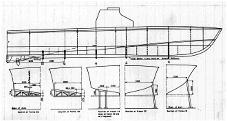 |
In certain circumstances variation from these positions can be accepted, but it is important to have a good support under frames 53 and 60, to take the weight of the engines.
The following should be observed during docking:
The watertight bulkheads are marked an the hull with smell triangular metal-plates below the rubbing stroke.
The center-lines of the rudders ore marked on the transom with smell triangular metal-plates below the water- line.
The boat centre line is marked on the deck with one triangular metal-plate at the transom and one abaft the forward hatch.
There must be a minimum distance of 1000 mm -- approx. 40 inches -- from the bottom of the keel to the floor of the dock to give clearance for the propellers.
The following distances must be kept between the bottom of the keel and the floor of the dock in order to carry out certain repairs:
To withdraw the propeller shaft a distance of 4800 mm -- approx. 16 feet -- has to be kept clear of obstruction- abaft the stern.
| Fig 9.4 Door and Locker Key Plan | 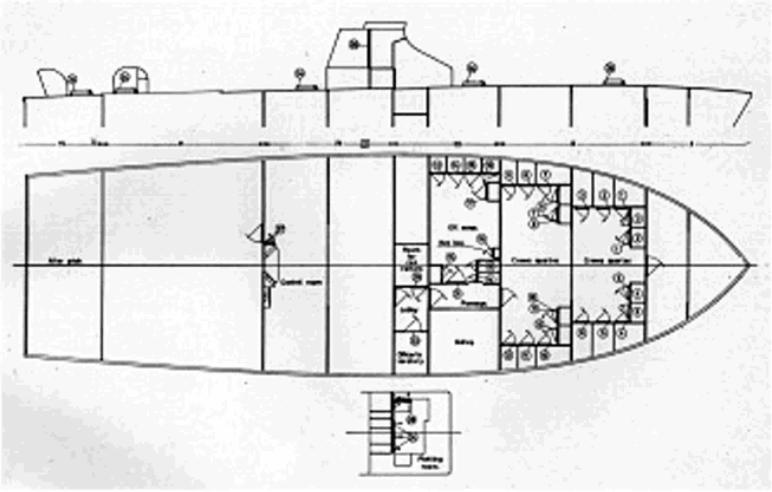 |
![]()