TECHNICAL |
PTF 9-16
|
|
|
[ Technical ] 3
|
ARTICLES:3.1 INTERIOR ARRANGEMENT |
FIGURES:3.1. General arrangement
Fig 3.1 General Arrangement |
The boat is divided by bulkheads into six watertight compartments. The main part of sections II and III are used as living quarters.
Berths for 18 men are provided as follows: Four men in section III (Officers' Mess), and twelve to fourteen men in section II (Crew's quarter). The rooms are fitted with tables for messing purposes and at least one locker per man for stowing personal effects.
The starboard side of section III holds the galley, fitted with on electric stove, a refrigerator, a working table, a sink unit and lockers, shelves and drawers for messing and galley equipment. The boat is fitted with separate lavatories for Officers and Crew.
Access from deck is through watertight hatches 550 x 580 mm -- 21,7 by 22,8 inches, and aluminum ladders, and access between the compartments is through watertight doors, 550 x 1250 mm -- 21,7 by 49,4 inches.
For the supply of fresh air and/or hot air, the boat is fitted with a ventilation system. (See article 4.9.1.) The venting from the compartments to atmosphere is through ventilators in the deck, some of which are fitted with electric fans for forced draft. (See articles 4.9.2. and 4.9.3.)
All the rooms are fitted with electric lighting. In addition to the ordinary lights, some of the compartments are fitted with a red light for use in darkened boat conditions, and in the event of main power failure an emergency light (24 V) is also fitted. (See article 5.)
| Watertight hatch | 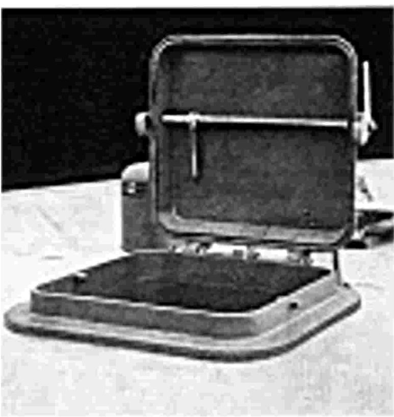 |
 |
The fore peak |
Access to the fore peak is from the Crew's lavatory through a large opening in the forward bulkhead frame no. 5.
The Crew's Lavatory (Section I) is fitted with two washbasins, a hand pump for freshwater, a hand pump water closet, (see article 4.8.3.), shelves and mirror, and stowing arrangements for oilskins. Access to the lavatory from the Crew's quarters is through a watertight door in the bulkhead.
| The crew's lavatory | 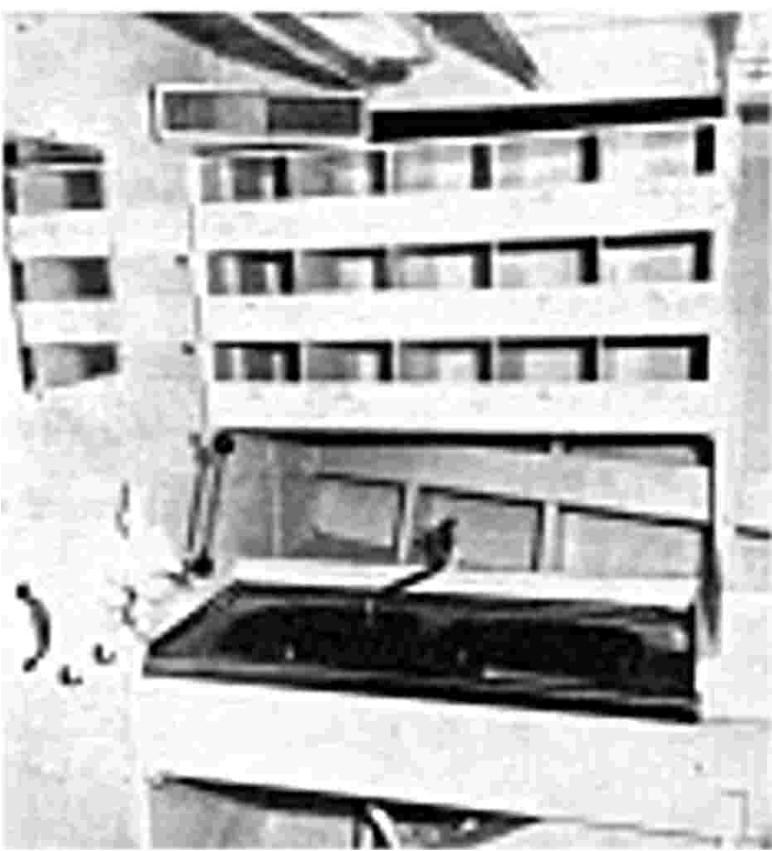 |
 |
The crew's quarters, section II |
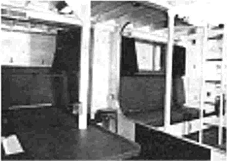
The Crew's Quarters (Section II) are divided into two parts, the forward and the oft quarters.
The forward quarter has accommodation for six ratings. It is arranged with three berths, three hanging lockers, and three smaller lockers on each side. Access from the upper deck is through a hatch on the center line and by aluminum ladder, from the lavatory through a watertight door in the forward bulkhead, and from the after Crew's quarter, through an opening 2400 x 1500 mm approx. 94 x 59 inches in the after bulkhead (frame 16).
The after quarter has accommodation for eight ratings. It is arranged with three berths, three hanging lockers, and three smaller lockers on each side. In addition there are two berths against the oft bulkhead. Further a folding table, three stools and a book shelf.
| The forward quarter | 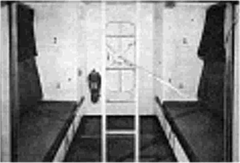 |
 |
The after quarter |
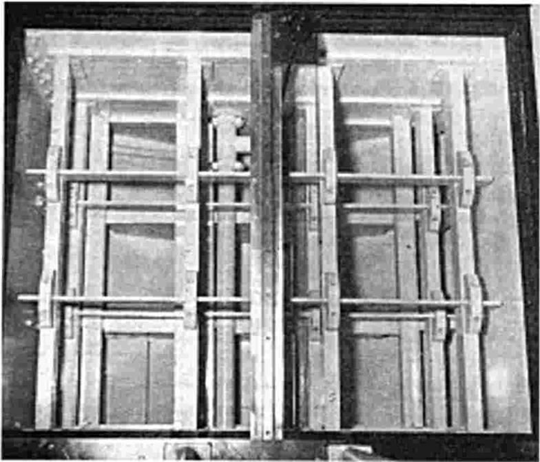
All the berths are fitted with mattresses of "Porolon", with canvas covers. The four inboard upper berths and the aft upper berth can be pivoted down to form backs, thus making the lower berths into settees for day use. Between the lower berths and the boat sides are stowage places for lifebelts, bedclothes etc.
The Passage (Section III). Through the watertight bulkhead between section II and III access is obtained through a watertight door to the passage, section III. The passage is fitted with gun racks and notice board. From this passage access is obtained to the upper deck by aluminum ladder and watertight hatch. On the port side there is a door to the officers' mess, and on the starboard side there is an opening to the galley. At the after end of the passage is an opening leading to the lobby.
The Officers' Mess, (Port side, Section III) is fitted with four berths, six small lockers, three hanging lockers, a folding table, two chairs with plastic covers, a book shelf and the key-locker. All berths are fitted with mattresses of "Porolon", with woolen covers, and the upper berths fold down to form settees.
| Officers' Mess | 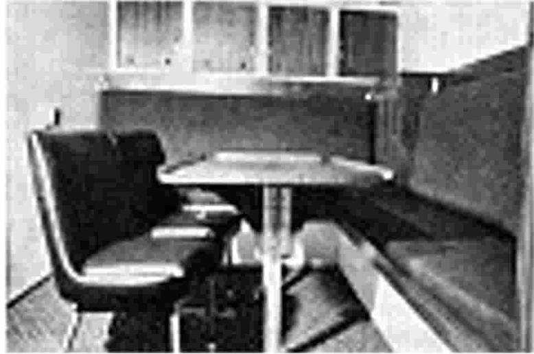 |
 |
The aft part of the galley |
The Galley, (starboard side, section III) is equipped as follows: On the oft bulkhead a stainless steel bench with a sink unit and a cock for drinking water (see article 4.8.1.). Lockers are fitted above and below the bench. A refrigerator is fitted below the inboard end of the bench.
On the outboard side there is a working bench with shelves and rocks above and lockers below. On the for- word bulkhead is an electric stove, and a bench fitted with drawers below. Above the electric stove is a hood and an electric extractor fan.
| The forward part of the galley | 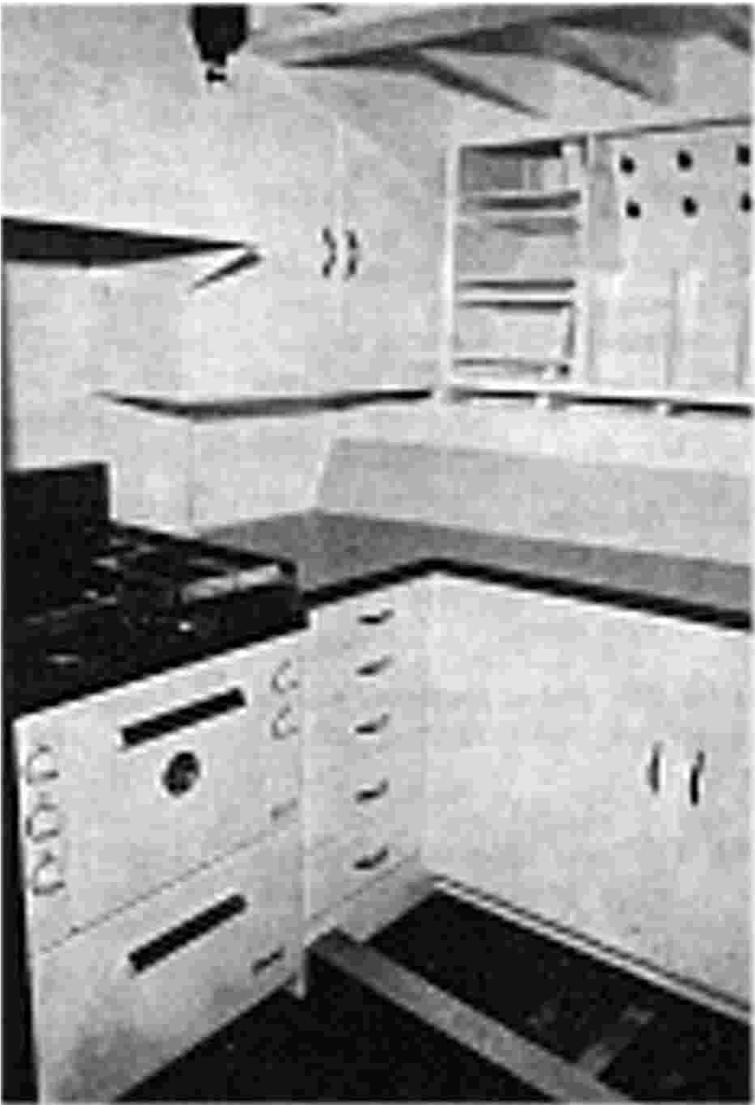 |
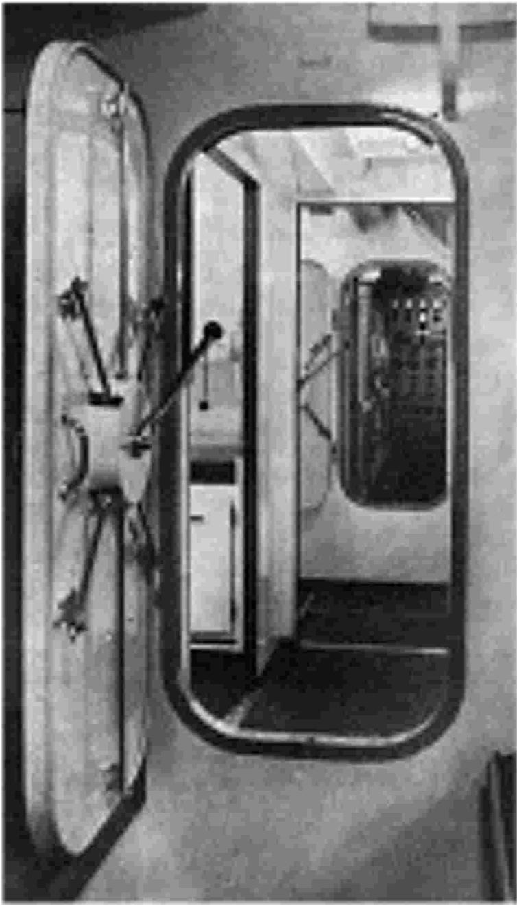 |
The passage and the lobby |
The Stove is of the type "Beho", B 3 S-P for 440 volt A.C. It has three hotplates with three-step switches and an oven controlled by thermostat (100-350deg C. -- 212-662deg. F. The stove has to be dismantled to be taken ashore.
The Lobby (aft part, section III). The aft end of the passage opens into the lobby. Through the door on starboard side is access to the officers' and P.O.'s lavatory. On the port side is a small door to the converter room below the plotting room. Also on this side there is a short ladder leading up to the plotting room.
Across the plotting room to the port side and down a short ladder there is access to the radio room. From the plotting room access is obtained to the bridge through a watertight door. At the other end of the lobby is a watertight door leading to the combined tank compartment and control room.
The Officers' & Petty Officers' Lavatory (aft stbd. side, section III) is fitted with a washbasin with a cock for cold water, a water closet with hand- pump (See article 4.8.3.), shelves and mirror.
The Converter room (center, aft part below the plotting room. Section III) holds the converters, transformers etc.
The Plotting Room, (center, aft part section III) is situated at a level half above and half below the upper deck, over the converter room. The room is fitted out with: Radar Display Unit, navigational and plotting aids electrical equipment, fuse boxes, switch panels etc.
On the forward side there is a plot-table. In the after part there are shelves, drawers and lockers. A water- tight hatch is fitted in the after part of the plotting room for direct contact between the bridge and plot.
| The plotting room | 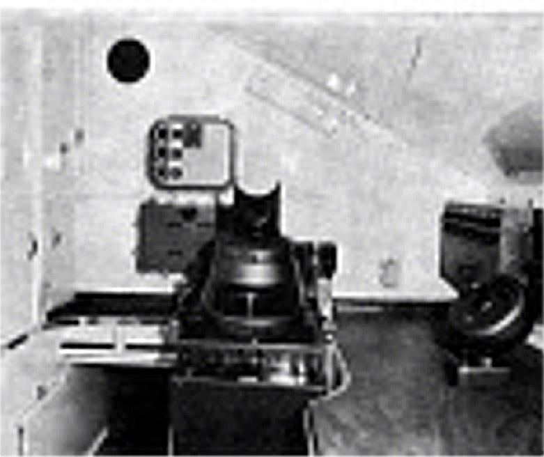 |
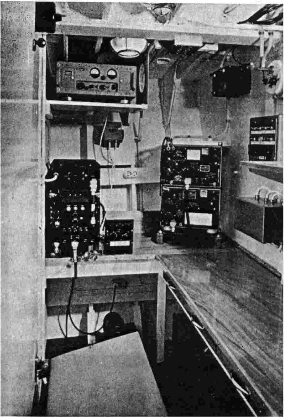 |
Alternative equipment of the radio room.
|
The Radio Room, (port side, aft section III) is fitted out with benches and shelves on the forward bulkhead and outboard side, as required for the radio equipment. A folding seat for the operator is fastened on the aft bulkhead.
Combined Tank Compartment and Control Room (Section IV). There are ten fuel tanks placed four on each side, and two in the center fwd. port of section IV. The tanks are placed on foundations fastened to the girders and frames. (See article 3.1.4. for removal.)
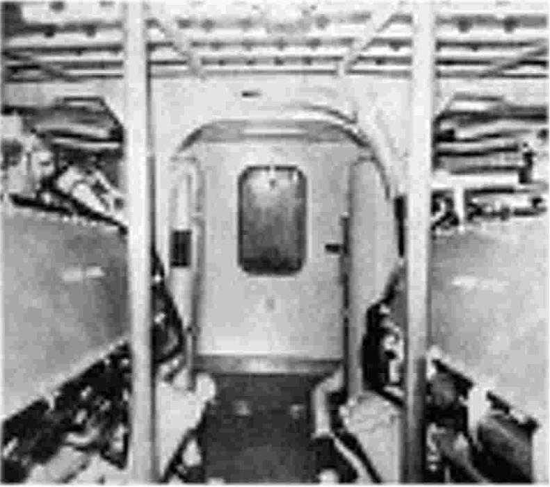
The after side of this section is fitted with the controls and instruments for the operation of main and auxiliary engines and electrical equipment. From the position in the chair the engine operator can view the engine room through a double glazed window. Access to the engine room is through a watertight door on the port side. The tool kit for the main engines is placed on the port side, below the step to the engine room door.
Access to the section is through a watertight door in fwd. bulkhead from section III and through a watertight hatch above the control room from the upper deck.
| The tank compartment | 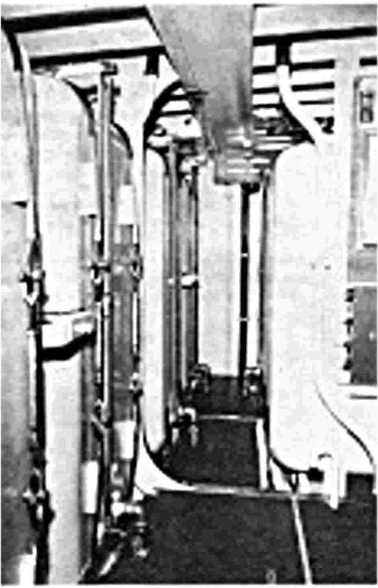 |
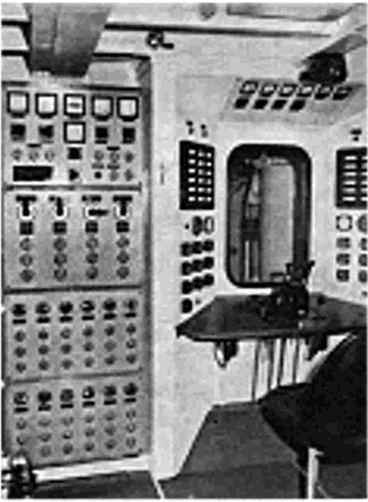 |
The control room |
Engine Room (Section V). For engine room arrangements see article 3.2. Access to the engine room from deck is through a watertight hatch at the after end and from the control room through a watertight door in the bulkhead.
After Peak. (Section VI). The following gear and equipment is installed in the after peak: The steering gear. (see article 3.2.2.), the air trunk and air splitters for the main engine air intakes, (see article 4.6.). The 9 inch exhaust pipes from the main engines also pass through this compartment (See article 4.5.).
There is stowage-place for 40 mm ammo. On the starboard side there is a stowage-place for the emergency steering tiller, and for the fuel-tanks dip stick. On the port and starboard sides, below the exhaust pipes, there are stowage-places for ropes etc.
| The after peak | 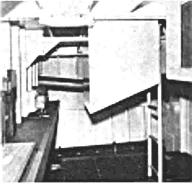 |
 |
Stowage for ammunition. |
Tools for propeller nut and shaft coupling nut, tool kit for auxiliary engines and the main engines hand turning gear are also stowed in this compartment. Access to the after peak is through a watertight hatch from the upper deck.
3.1.3. StoresBesides the stowage facilities mentioned in article 3.1.2. ammunition stowage is provided below the floorboards in the Crew's quarters and the passage. Provisions can be stored in special watertight cases below the floorboards in the passage and the galley. 3.1.4. Removable deck sectionsFor the removal of assemblies which are too big to pass through the watertight hatches, removable sections are provided.
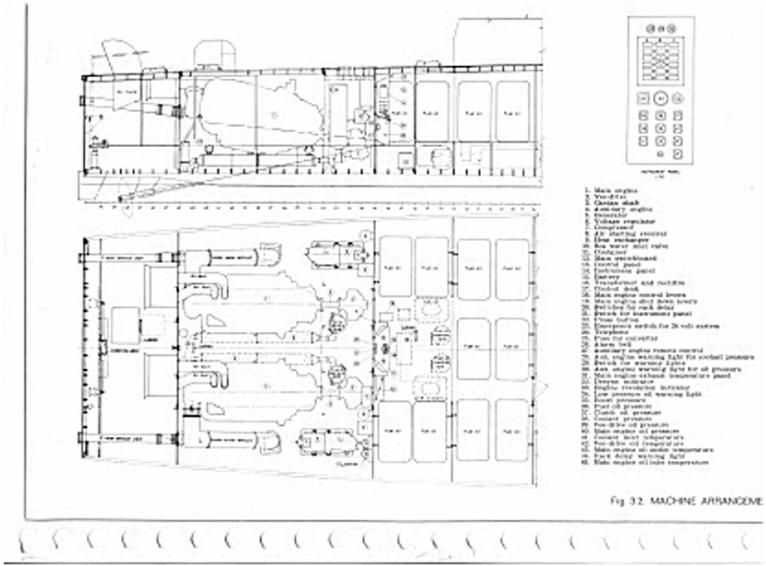
3.2. MACHINERY ARRANGEMENT3.2.1. General RemarksThe boat machinery is placed in two compartments, sections IV and V. The main and auxiliary engines, vee-drives and all ancillary equipment are installed in section V. The main switchboard, the control panels complete with main and auxiliary engine controls and associated instruments are installed in section IV. These compartments are divided by a watertight bulk- head fitted with a watertight door. An inspection window is fitted in the center of the watertight bulkhead, to give an easy view of the engine room from the operator's seat in the control room. The main engines are operated from the control room or the bridge by remote controls (see article 3.3.1). It is not necessary to keep a permanent watch in the engine room, provided periodical inspections are carried out. (See operating guide article 8). There are no storage tanks in the engine room. The ten main fuel tanks are installed in the combined tank compartment and control room. The storage tanks for lubricating oil and coolant ore placed below the floor- board in this compartment. Rubber hose connections and "Aeroquip", flexible pipes ore used throughout the installation to resist vibration. All piping, wiring and control systems passing through the bulkheads are made watertight. More detailed descriptions for main and auxiliary engines ore given in article 4.1. to 4.6. Some deck sections are made removable for the maintenance and repair of engines, tanks and other equipment (see article 3.1.4).
3.2.2. Engine Room (fig. 3.2.)The Main Engines (1) are installed one on each side of the center line with the output coupling facing for- ward. Power is transmitted through a flexible cardan shaft to a vee-drive and thence to the propeller shaft. The vee-drive has on included angle of 18" between the input and output shafts (see article 3.3.3). The "Deltic" engines are manufactured by D. Napier & Son Ltd., England. The type T18-37 K is a 18 cylinder, straight-forward, high-speed, two-stroke, uni-flow engine that is pressure charged and liquid cooled. The rated output at 2100 R.P.M. is 3100 b.h.p. The engine is fitted with a bi-directional gearbox with a ratio of 1.8574 : 1 both clockwise and anti-clockwise. The "Deltic" engines acquire the name from the inverted delta or triangular configuration of the cylinders. Each cylinder block forming a side of an equilateral triangle with a crankcase at each corner. As the engine is an opposed-piston type, this arrangement enables each crankshaft to serve two adjacent cylinders, two connecting rods being attached to each crank throw.
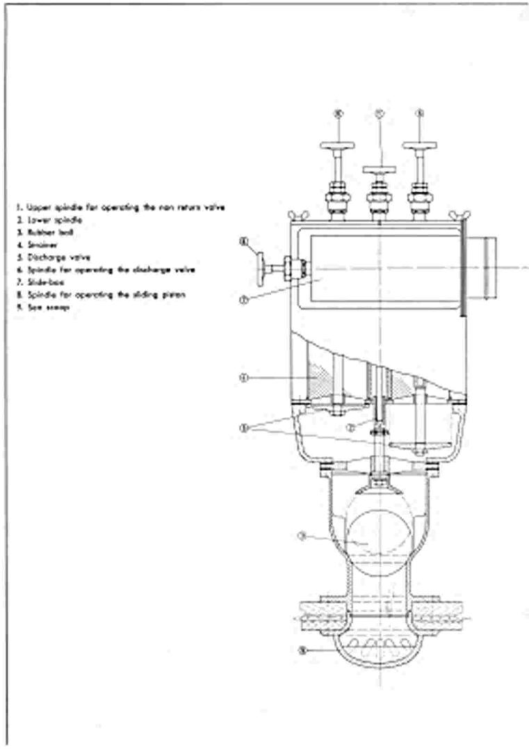
Phasing gearing at the driving end links the three crank shafts and combines their outputs in a common drive to the hydraulically operated ahead and astern clutch and the reduction gear output coupling. The two engines are similar. To obtain opposite rotations of the propellers in ahead selection, oil pipes for the hydraulic clutches have merely to be cross-connected on one of the engines. Any engine can then be used in port or starboard position. Each engine is mounted on four aluminum foundations, fastened to "A", and "B," girders. The mounting feet are fitted with rubber bushings for flexibility and the free-end feet are free to move axially for expansion purposes. The sea water is delivered by an engine driven pump to the heat exchanger and oil cooler and is then discharged overboard through the 9 inch exhaust pipes. Thermostatic valves regulate the temperatures of the coolant and oil. The Sea Water Inlet Valves (10) are installed in the oft part of the engine room, one on each side of the boot center line. They are made of aluminum bronze by the boat yard in accordance with fig. 3.2.a. In principle it is a non return valve fitted with duplex strainer. The non return valve comprises a screw down vertical spindle, located at center, and a loaded rubber ball of a weight suitable to hold sufficient water for priming the pump before starting the main engine. The duplex strainer comprises the two removable strainers elements, each in a compartment with a closing off discharge valve operated by a vertical spindle, and a sliding piston selector valve operated by a longitudinal spindle located near the top of the strainers housing. By this arrangement one of the strainers can be selected for use whilst the other is closed off and the strainers element can be removed for cleaning. Directions for use are mounted on bulkhead, above the inlet valves. Miscellaneous: Besides what has already been described, the engine room is fitted with a small container (11) on the for- ward bulkhead on the starboard side, for cleaning rags etc. A watertight shutter is fitted in the aft bulkhead, on the port side of the boot center line, for circulation of air from the engine room to the oft compartment. All valves, pipes, pumps, filters, tanks etc. are described in "Descriptions of systems", articles 4.1 - 4.6.
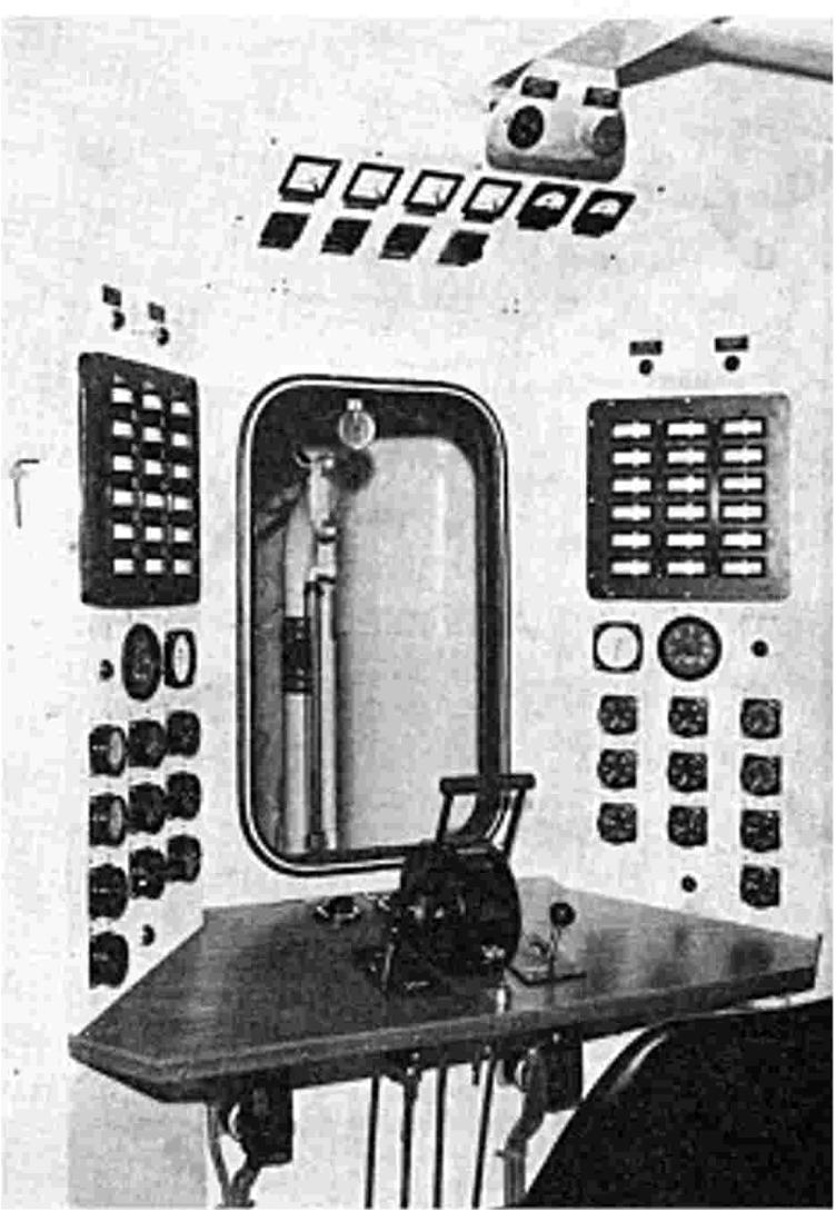
3.2.3. Control Room (fig. 3.2.)The control room is described in article 3.1.2. A further description of the equipment in the control room is given below. The main switchboard (12) and control panel (13) for electric instruments and switches are described in article 5.1.3. The instrument panels (14) for port and starboard main engines and auxiliary engines are fitted with all the engine instruments. For details, see fig. 3.2. The storage battery (15) is placed below the floor- board in a watertight box, made of marine type ply- wood. Venting from the battery box is through the ladder to deck. For more details see article 5.1.4. The Transformer and Rectifier (16) ore placed below the floorboards on the outboard side of the girder, port side. For more details, see article 5.1.4. The main engine control desk (17) is placed in the oft part of the combined tank compartment and control room. It is fitted with the following:
(19) Main engine shut-down levers (20) Switches for rack delay system (21) Switch for the main engine oil warning lights and rack indicators. (22) Press button for signal to the bridge. Under the control desk the following is fitted:
(24) Receptacle for telephone. (25) Fuses for converter. (26) Alarm-bell. Above the engine control desk, under deck, are the remote controls (27) for the auxiliary engines. Access to the back of all instrument panels is obtained either by hinged panels or access doors. All instruments, switches and warning lights are marked with engraved labels.
|
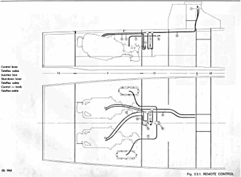
3.3. MECHANICAL ARRANGEMENTS3.3.1 Remote ControlDescription (fig. 3.3.1.) The main and auxiliary engines are fitted with a mechanical type remote control to the control room. The type used is "Teleflex Marine Controls", made by Teleflex Products Ltd., Essex, England. Main Engine, Gear changing and Speed-control. The control system is designed to permit operation of the engines from either the control room or the bridge. The function of gear changing and speed selection is carried out by a lever (1) from either the central room or the bridge. The levers are connected in tandem through a single cable (2) and junction box (3) to both the hydraulic governor and the hydraulic control unit. This arrangement permits the automatic selection of the correct engine speed during gear changing and the retention of the required gear during subsequent speed changes. For further information, see "Deltic" Maintenance Manual, Publication M1, article 7.1. Main Engine Shut-down. Each engine is stopped by a hand-operated shut-down lever (4) situated in the control room beside the speed control lever. When lever (4) is moved to "Stop", the shut-down cable (5) moves the governor shutdown lever and shutdown probe lever, which in turn depresses the servo to stop the engine.
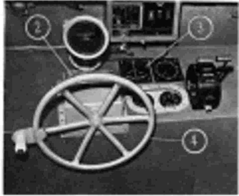
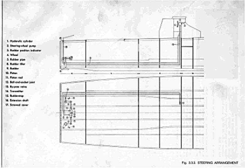
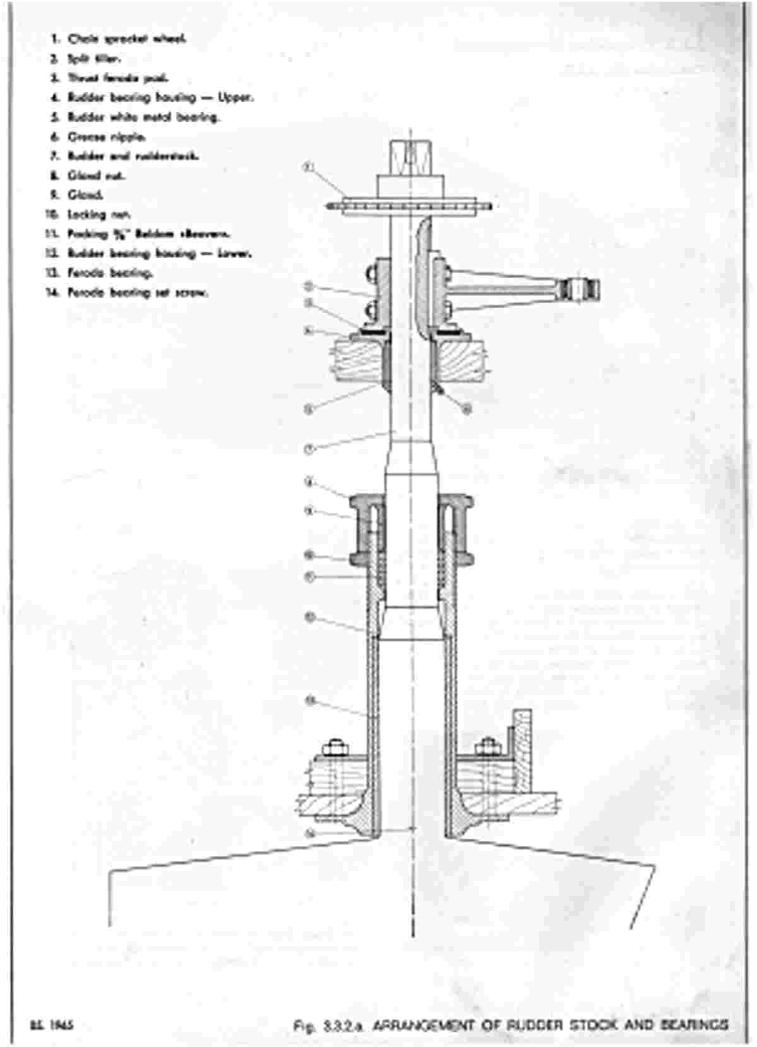
Auxiliary Engines speed control. The auxiliary engines remote speed controls are mainly fitted to adjust the voltage and frequency on the gene- rotors. (See article 8.5). The control-knobs (6), one for each engine, are located above the main engine control panel in the control room. The control is connected to the auxiliary engine governor through a "Teleflex,"-cable (7). 3.3.2. Steering ArrangementDescription (fig. 3.3.2.) The steering arrangement consists of three main components: 1) Rudders with rudderstocks, bushing and stuffing boxes. 2) Steering equipment. 3) Emergency steering. 1. Rudders. The boot is fitted with two cantilever spade rudders, designed and manufactured by the boat yard. The rudder and stock are made in one piece of aluminum-bronze. (Weight 140 kg. -- 310 lbs.) The rudder-stock tubes with flanges and stuffing boxes are made of aluminum-bronze, and the bearings and thrust are mode of "Ferrobestos,". The flanges are fastened to the hull with through bolts of stainless steel. (See fig. 3.3.2 a with reference list). The rudders are set parallel in relation to the boat centre line, this has been found by experiment to be the best compromise between boat speed and maneuverability. If a rudder is changed it can be necessary to check the rudder angle. 2. 2. The steering equipment is hand-hydraulic and consists of a hydraulic cylinder with a piston type IR 2/60 (1), pillar with steering-wheel, pump and expansion reservoir, type H 60 (2), a rudder position indicator (3) and suitable pipes and connections between the wheel-pump and the hydraulic cylinder. The wheel-pump (2) placed on the port side of the bridge is operated by the wheel (4). By turning the wheel, the oil is pumped through one of the pipes (5) to the corresponding side of the hydraulic The steering apparatus. cylinder (1). The oil returns to the pump through the other pipe (5).
The hydraulic cylinder (1) is placed in the after compartment (Section VI) between the two rudders. The piston in the cylinder is connected to the rudders (9) through the tillers (8) and the connection rods (10) and (11). The connection rods ore fitted with adjustable universal joints (12). The hydraulic cylinder is fitted with a safety-valve (13) set to open at a pressure of 40 kglcm2 -- 570 Lbs.sq.in. The wheel-pump (2) is fitted with a device, restricting any movement on the rudders from sources other than the pump. For emergency steering or other reasons, the rudders can be moved freely by screwing in the safety valve (13) thus permitting the oil to pass from one side to the other in the cylinder.
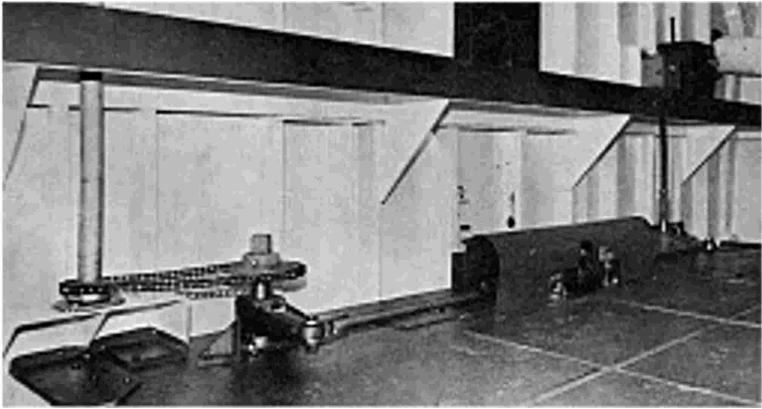
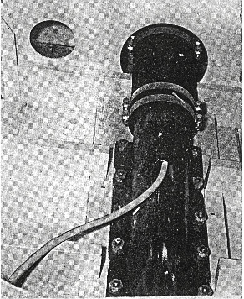
The rudder position indicator (3) is placed on the bridge, and is connected to the transmitter (14) by electric cables. The transmitter is mechanically connected to the port rudder, and the system is electrically connected to the 115 Volt A.C. supply-lines. (See fig. 5.1.1. and 5.1.5.). Rudder stop blocks (15) are fitted for both rudders. 3. Emergency steering can be connected to the starboard rudder. A vertically mounted shaft (16) is connected to the starboard rudder-stock by means of a chain and chain-wheel with 2 to 1 reduction. The upper part of the shaft can be lifted and lowered approx. 50 cm -- 20 inches. When not in use, the shaft is lowered and the opening in deck is sealed by a screwed cover (17). When in use the shaft is lifted and fitted with a hand tiller. When using the emergency steering, the safety valve (by-pass) (13) must be screwed in. 3.3.3. Propulsion ArrangementDescription (fig. 3.3.3). As previously described in article 3.2.1. each engine installation including vee-drive, propeller and propeller shaft is entirely independent of the other but identical in arrangement.
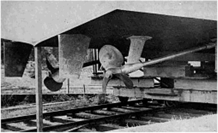
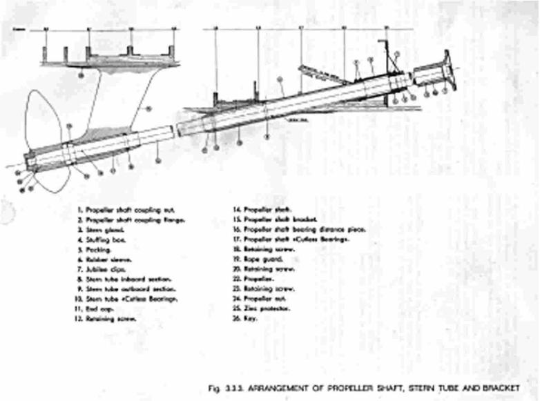
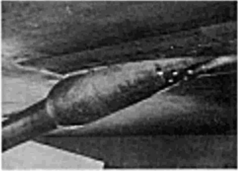
Each propeller shaft (14) is supported in a stern tube (8) and (9) and propeller shaft bracket (15) at an angle of 12" to the base line. It is directly coupled to the out- put coupling flange of the vee-drive. The vee-drive with on included angle of 180 is mounted as described in article 3.2.1., which therefore allows the engine to assume an angle of 6" to the base line. From the input coupling flange of the vee-drive a cardan shaft is secured to the engine output coupling flange. Each Stern Tube is constructed in two sections of aluminum-bronze castings, one inboard (8) and the other outboard (9) on either side of the hull as shown in the figure. Each section with its integral base plate is secured by through bolts to a stiffened section of the hull in the vicinity of the stern tube. Port and starboard construction are contoured to conform with the bottom of the hull, The outer section contains a Cutless Bearing (10) of 4'/4" dia. type "Nicety" made by Goodrich Cutless Bearings. Water lubrication of this bearing is partly supplied from holes drilled at the forward end of the costing. To the forward end of the inner section a self aligning stuffing box (4) and a stern gland (3) is secured by means of a special rubber sleeve (6) and clips (7). For cooling and lubrication purposes salt water is supplied from the main engine salt water circulating system to the casting as shown in the figure. The Propeller Shaft Brackets (15) are contoured for port and starboard sides to conform with the bottom of the hull, but in all other respects they are identical. The brackets of cast aluminum-bronze are of "P",-form design. Each bracket is secured to a stiffened part of the hull by through bolts. A Cutless Bearing (17), of identical dimensions and type as fitted to the stern tube, is also fitted to the boss of the bracket. Lubrication for this is supplied by water taken at the forward end of the boss. Each Propeller Shaft (14) of aluminum-bronze designed so that the ends are identical and in certain circumstances the shaft could be reversed. The shaft coupling flange (2) is secured by a key (26) and a nut (1), and the nut is locked by a special plate arrangement. The Propellers (22) of aluminum-bronze castings are similarly secured by key (26) and nut (24), but the locking for the nut is by a retaining screw (23) through the nut flange to the propeller boss. The propellers have the following dimensions: Diameter 47", Pitch 62.4", Weight 120 kg -- 265 Lbs., and are designed in England by Mr. Selman in co-operation with Boat Services Ltd. A/S. When viewed from the after end, the port propeller turns in an counterclockwise direction while the starboard turns in the clockwise direction. For protection against electrolytic corrosion zinc anode (25), is mounted at the brackets. WARNING: |
|
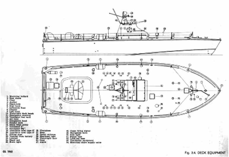
3.4. DECK AND SUPERSTRUCTURE - EQUIPMENT3.4.1. Mooring Equipment (fig. 3.4.)The boat is fitted with five mooring bollards (1), three on the fore deck and two on the after deck. The bollards are fastened to the deck by through bolts. The deck is strengthened under each bollard. A bow chock (2) is mounted on the stem to lead the ropes for mooring and anchoring. Four cleats (3) are fitted along the boat's side -- two on each side -- for fastening of fenders etc. A "Danforth," anchor (4) of 45 kg -- 100 Lbs -- is placed on the fore deck and lashed to the deck. The anchor has a 7,5 metre, approx. 24 feet long, galvanized '/2" dia. chain, and a 90 metre -- 295 feet -- 1" die. nylon rope. The chain and rope ore usually stowed in the fore peak with access to the deck through a hand- hole (5). When stowed, the end of the chain is fastened to a hook on the deck-stringer near the hand-hole. The boot is also equipped with four 1" dia. nylon ropes of 30 metres -- approx. 98 feet length, two heaving lines, four inflated plastic fenders, and two boot hooks (61. 3.4.2. Lifesaving Equipment (fig. 3.4.)The boat is equipped with two -- 10 man, automatically inflatable rubber floats (7). When the hook, fastening the float to the cradle is released, and the float thrown overboard, it will automatically release the mechanism to inflate the float with CO2 gas, which is stored in a bottle. The boat is also equipped with a plastic dinghy (8), and two life rings (9). Lifebelts are not delivered with the boot, but may be stowed in the racks adjacent to the berths. Because of the speed and maneuverability of these boots, they are very quick in movements, especially in rough weather. Care should therefore be taken when moving on deck. 3.4.3. Miscellaneous Deck Fittings (fig. 3.4.)
(11) Emergency steering (see article 3.3.2). (12) Ventilators for venting fuel tanks (see article 4.1.1.). (13) Air inlet to the main engines (see article 4.6.1). (14) Hatch and air inlet to the engine room (see article 4.6.1). (15) Header tanks for main engines cooling system (see article 4.3.2). (16) Flush deck hand bilge pumps (see article 4.7.3). (17) Ventilators for venting compartments below deck (see article 4.9.2.). (18) Large ventilators with fans for galley and converter rooms (see article 4.9.2). (19) Cowl-type ventilators for living quarters etc. (20) Large type natural draft ventilators for engine room. (21) Filling pipes for storage tanks (see article 8.7). (22) Venting from storage battery box. A 6 mm -- approx. '/4 inch. -- plastic coated wire lifeline (23) runs from a tripod jack staff-holder on fore deck through stanchions on both sides, to a tripod flagstaff-holder at the transom. The lifeline is fitted with pelican hooks at suitable positions. The oft stanchion also holds the stern lantern (25). When the boat is fitted out as a MTB, the lifeline will be fastened to eyes on the torpedo tubes. A hand rail (24) is fitted on the front of the bridge.
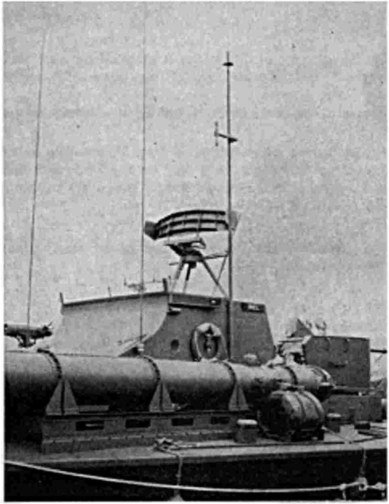
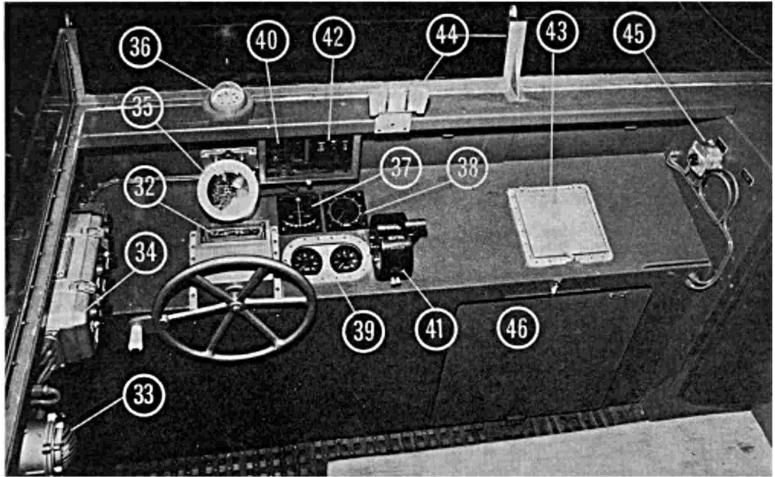
3.4.4. Superstructure (fig. 3.4.)The superstructure amidships is a combination of open bridge and plotting room, and is mode of plywood and covered with Dekaplex. A windscreen of Plexiglas (26) is fitted on the top of the open bridge, on the front and sides. On the oft port of the bridge is mounted an aluminum mast (27) for radar-antenna (28), top-lantern (29), signal flags etc. The most can be folded down when necessary. Access to the open bridge is from the plotting room through a watertight door (30) on the starboard side and from the deck through a door in the aft bulkhead (31). This door can be locked. The following equipment is mounted on the bridge: (See photo).
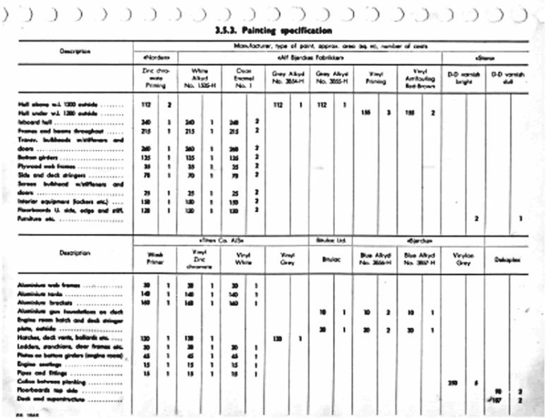
(33) Alarm from control room. (34) Control box for navigation lights, horn and alarm buttons. (35) Gyro compass. (36) Magnetic compass. (37) Rudder position indicator. (38) Speed indicator. (39) Engine revolution indicators. (40) Remote control for gyro. (41) Engine control levers. (42) Instrument for log. (43) Watertight shutter to plotting room. (44) Bracket for gyro compass. (45) Receptacle for telephone. (46) Folding chart table. On the top of the superstructure at the oft end (see fig. 3.4), the main alarm (47) and the cease firing signal (48) are installed. On the port side the navigation horn (49) is placed, and on starboard and port sides the green and red side lanterns (50) are installed. The bridge is also fitted with: Grating on the floor. Open locker for "Aldis,"-lamp and binoculars. Two openings in the superstructure abaft the open bridge, one on each side, for the signal man (51) and look-out (52). The ventilation equipment (53) is installed beneath the signal-man's position on the port side (see article 4.9.1), and the electrical shore-supply cable (54) is stowed beneath the look-out's position on the starboard side (see article 8.5.6). There are also lockers for signal flags on the port side and stowage for pyrotechnics equipment on the stor- board side. All lockers are fitted with drainage holes. 3.5. PAINT3.5.2. The paint compositionThe types of paint used, and the numbers of coats applied are given in the table at the end of this article. The various paint compositions are shown in the following list: WOODEN MATERIALS:
Anti-fouling bottom paint: "Bjercke Trans-ocean Vinyl" First coating of paint: "Bjerckes" No. 1505 H, 3854 H and 3856 H Finishing coat of paint: "Bjerckes" No. 3855 H, 3857 H and Oxan Enamel no. 1 Furniture etc.: "Stars" D.D.-varnish
3.5.1. Maintenance of painted surfacesWhen the boat is delivered from the yard it is painted as specified, however, the pointed surfaces have to be maintained. The maintenance should be carried out before the paints are worn through. It is very important that the surfaces to be painted are clean and dry, as the main reason for painting is to keep the dampness or wet out of the wood. As the point is water resisting, it will not penetrate the wet surface, but will dry without adhering. When the moisture in the wood evaporates, the pressure will make blisters which easily scale off. Old, loose point, grease and oil should be scraped off and the surfaces washed and thoroughly dried before new paint is added. Where the paint has been worn off, priming paint in accordance with the specification should be used. As all types of paint do not mix or adhere to each other, it is recommended to use paint of the same basis as that originally used by the yard. If another type of paint is to be used, a specialist should be asked for recommendations. Special attention should be given to all "Vinyl", types of point as these contain very strong solvents. They should never be painted on the top of old oil paints or Alkyd paintsThe deck and superstructure are covered with Dekaplex. This coating can be repaired in the same way as for ordinary paint (described above). NOTE: Do not use thick layers of paint, as it will only increase the weight of the boat and shorten the range.
Fig 3.5.3 Painting Specifications
|