|
PTF 9-16
|
|
|
[ Technical ] 4
|
Articles:4.1. FUEL SYSTEM |
Figures:4.1 Fuel system4.1.3. Tank sounding 4.2. Lubricating system 4.3.1. Sea water cooling system 4.3.2. Fresh water cooling system . 4.4. Air starting system 4.5. Exhaust system 4.6. Air supply 4.7. Draining system 4.8. Fresh water and sanitary 4.9. Heating and ventilation
|
The fuel oil system consists of ten storage tanks (1), two manifold tanks (2), change-over filters (17), hand priming pumps (21) and suitable fittings and pipelines.
The Storage Tanks (1) which are identical in sire and shape, are placed on either side of the center line on each side and two in the center of section IV. Suitable rubber lined foundations which are placed level with the floorboards, are secured to the bottom girders. On these the storage tanks are mounted and secured by steel wires to the frames and stringers.
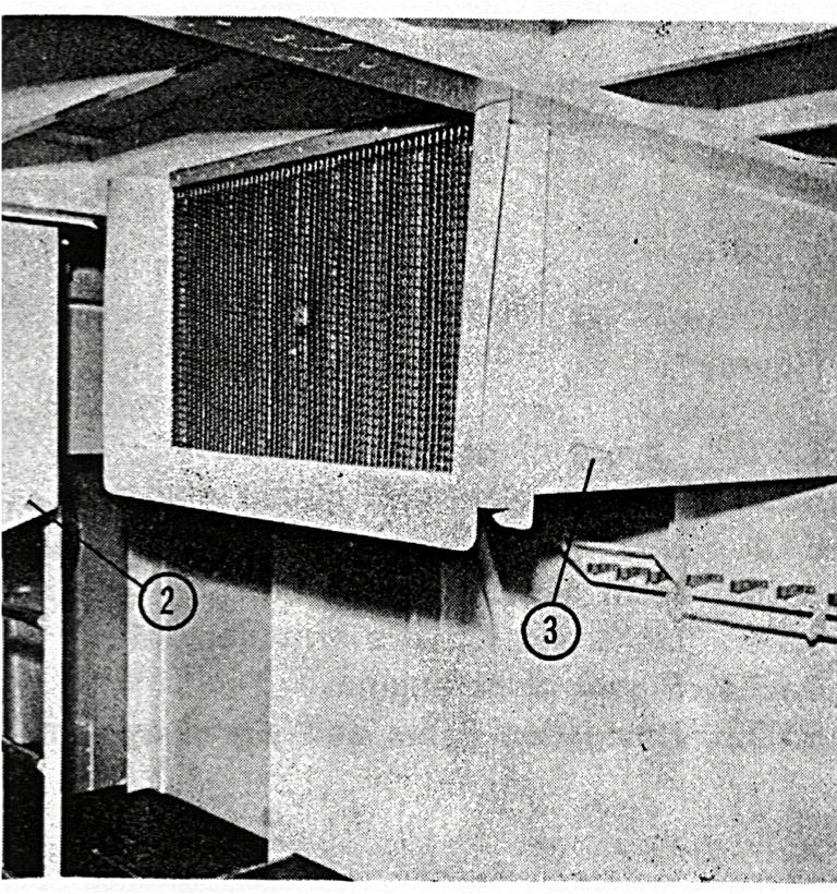
The Manifold Tanks (2) which are identical in size and shape, are placed on either side of the center line in section IV below the floorboards and mounted on rubber lined foundations, which are secured to the bottom frames and bulkhead.
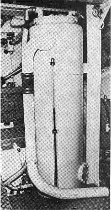
| The manifold tank, looking from above. | 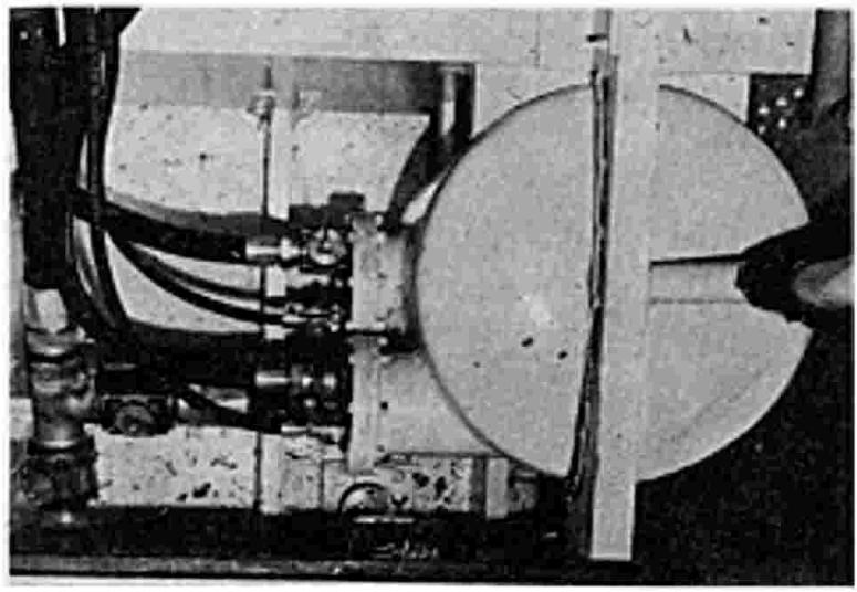 |
Filling, Venting and Draining. The storage tanks are filled through deck fittings and filling pipes (3). The tank soundings can be mode through this same fitting by a dipstick which is kept on the bulkhead in the after peak frame 64 starboard side. Each tank is vented through a pipe and ventilator (4) to atmosphere above deck. The manifold tanks (2) are fed by gravity from the storage tanks by opening valves (6) and (9) and ensuring that vents (5) are clear.
3-way cocks (20) should be supply from either the fwd. The port and starboard fuel connected by a valve (8) for positioned to select fuel tanks or the after tanks. supply systems are cross-emergency use.
The tanks and system can be drained by opening valves (25) on the manifold tanks, this will leave a small residue in the bottom of the manifold tanks and can be removed by a portable pump connected to valve (25).
Main Engine Fuel System. The fuel system from the manifold tanks (2) to the inlet on the engines consists of supply valves (15), change- over filters and associated valves (17) and pipelines (16). The change-over filter and valve allow one filter to be cleaned with the engine running subject to correct arrangement of the valve on the filter.
The supply pipelines (16) are cross connected in the engine room through valve (7) and the return pipelines (18) are cross connected through two 3-way cocks (10) and pipeline (22). These cross connections are for emergency use.
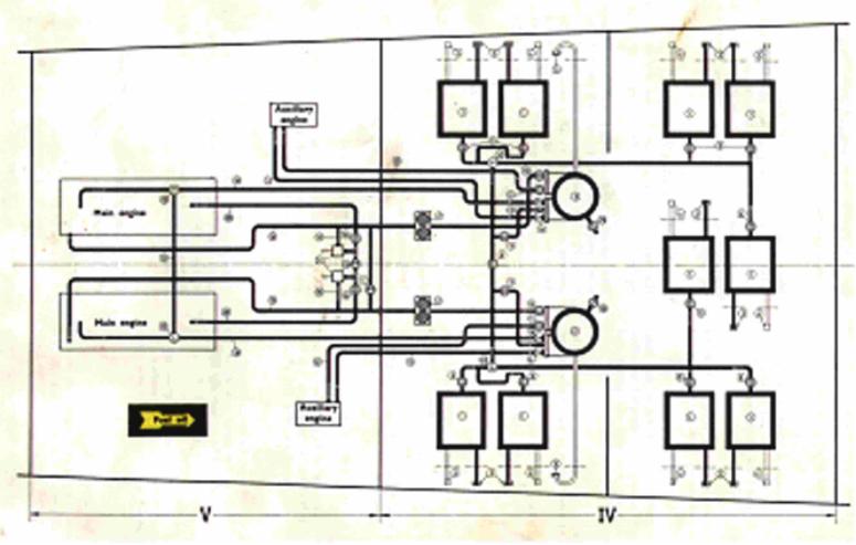 |
Fig 4.1. Fuel System | 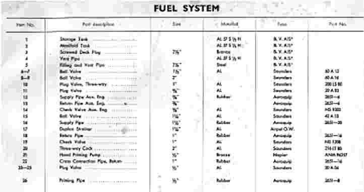 |
Main Engine Priming. The main engine fuel system must be primed before starting. This is accomplished by using hand priming pump (21) and valves (24). The hand pump suction is taken from pipeline (16) and discharged through valve (24) and pipeline (26) to two stage valve on the engine.
| Hand priming pumps (2). | 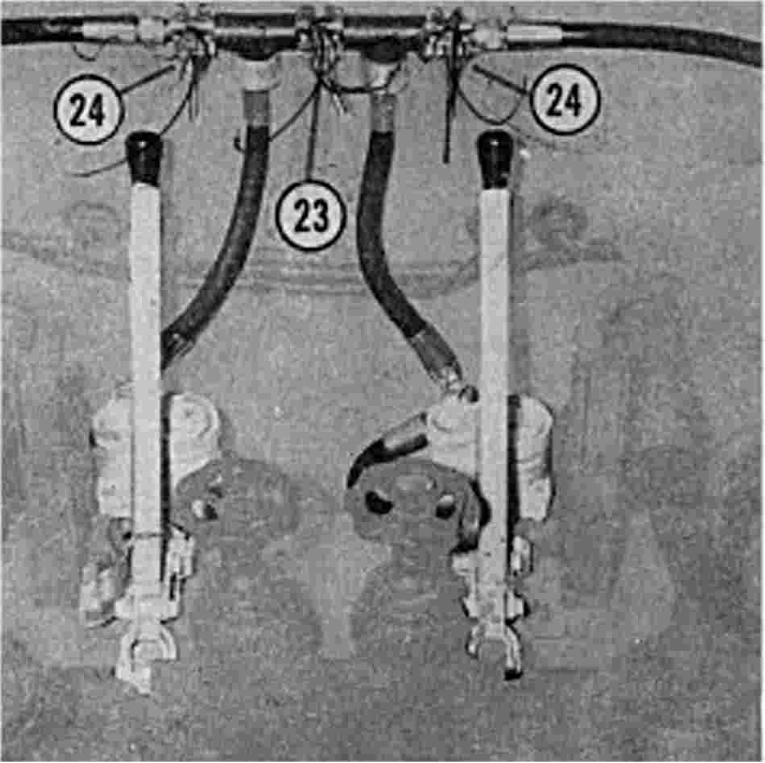 |
The two stage valve distributes fuel to the starting accumulators and the engine fuel system. (See Deltic Maintenance Manual,). In the unlikely event of a failure of one priming system valve (23) is fitted as a cross connection between port and starboard installation.
Surplus Fuel from the outlet of each engine pressurizing valve is returned through pipeline (18) and non- return valve (19) to the manifold tank.
Auxiliary Engine Fuel. The auxiliary fuel system is supplied from the manifold tanks (2) through valves (11) and pipelines (12). Surplus fuel is returned through pipelines (13) and non- return valves (14) to the manifold tanks.
Storage tanks (1). The storage tanks are all-welded of seawater-resistant aluminum. They have horizontal and vertical internal, bulkhead stiffeners. Tank capacity: 2300 liters each -- approx. 507 imp. Gals -- 610 U.S. Gels. The tanks are pressure-tested to 1 kglcm2--14.2 Lb/sq.in.
Manifold tanks (2). The manifold tanks ore all-welded of seawater-resistant aluminum.
Tank capacity: 100 liters each -- 22 imp. Gels. -- 26.5 U.S.
Gels.
The tanks ore pressure-tested to 3.5 kg/cm? -- 49.7 Lb/sq.in.
|
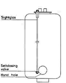
The fuel oil storage tanks are equipped with external contents sight glasses. To use the sight glass the self-closing valve at the bottom should be pressed in, and then the tank contents can be read on the indicator scale. |
 |
As shown on fig. 4.2. the lubricating system to each engine installation, including the vee-drive, is entirely independent of the other and only the storage tank (1) is common to both.
Each engine lubricating system is identical and consists of a service tank (2) and oil cooler (30) complete with thermostatic valve (22) and hand priming pump (13) and suitable fittings and pipelines.
The associated vee-drive system is separate from the engine system, but receives oil from the same service tonk, see later details.
The Storage Tank (1) is placed below the floor- board oft of frame 43 in section IV. Mounted on rubber lined foundation between "A," and "B," girder and secured to the girders.
Each Service Tank (2) is identical and secured by welded brackets and other fittings to top of "A," stringer.
The Oil Cooler (30) is port of the combined heat exchanger which is secured to the frames beneath the floorboards adjacent to the center line.
Filling, Venting and Draining. The storage tank is filled through deck fitting and filling pipe (3), and is vented through a gooseneck (4) above the floorboard in section IV. On the top of the tank there is a screwed plug (5) to which a dipstick is fastened. A drain valve (6) is fitted to the tank.
Subject to correct positioning of 4-way valves (12) and (17) the service tank is filled by the hand pump (13) from the storage tank through non-return valve (14) pipeline (15) and filter (16).
| Figure 4.2 Lubricating System | 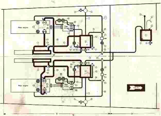 |
 |
The service tank |
The service tank is vented from the cover through pipe (7) and oil separator (8) to the boats side below the gunwale. The oil separator should be periodically drained through valve (9).
Each tank is fitted with an oil level sight glass (10) on which maximum and minimum levels ore marked. The sight glasses ore easily seen from the control room window.
Main Engine Lubricating System. Each engine oil pressure pump (27) receives oil from the service tank through valve (19) and pipeline (20). The main engine oil filters (28) ore integral with the "Deltic" engine.
Oil is returned from the engine bottom crankcase to the service tank (2) by the engine mounted scavenge oil pump (29). A thermostatic valve (22) proportions the oil flow through a pipeline (21) to the cooler and through the by-pass opening in the thermostatic valve, according to a pre-determined temperature setting, and the oil is returned to the service tank (2) through a de-aerator fitted inside the tank.
Main Engine Priming. Before starting the engine, the oil system MUST be primed. Open supply valve (18) on the service tonk and correctly position valves (12) and (17). Using hand pump (13) oil is pumped to the priming connection on the engine via pipe (33).
Vee-drive Lubricating System. The Vee-drives are lubricated from the main engine service tanks to simplify the cooling arrangements.
Each vee-drive has its own oil pressure and oil scavenge pump and suction and delivery oil filters. By opening valve (23) oil is delivered to the supply filter (25) and to pressure pump (31) then to oil pressure filter (26) and thence to the vee-drive sparge jets. From the bottom of the vee-drive oil is removed through a strainer incorporated in the vee-drive by scavenge pump (32) and returned to the service tank.
The double oil pressure filter (26) can not be cleaned whilst running.
Thermostatic Valve. The thermostatic valve (22) is operated in conjunction with the oil cooler, and the temperature control is obtained through a wax filled capsule operating a rotary valve. This is fitted to the outlet from the oil cooler to obtain the required temperature at the engine inlet.
Wax filled capsule control in the thermostatic valve is not adjustable. If climatic condition necessitate changing the grade of oil used in the engine the valve must be re- moved and a new valve fitted to suit altered climatic conditions.
In the event of a sudden rise of temperature on emergency control is fitted and the rotary valve can be manually operated to pass all oil through the cooler. After such an Emergency the thermostat should be re- moved and checked for correct operation.
Storage tank. The storage tanks is all-welded of seawater-resistant aluminum. It has two internal bulkhead stiffeners.
Tank capacity: 270 liters -- 60 imp. Gals -- 71'21.S. Gals.
The tank is pressure tested to 0.75 kg/cm2 -- 10.7 Lb/sq.in.
 |
Seawater Cooling System |
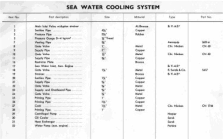 |
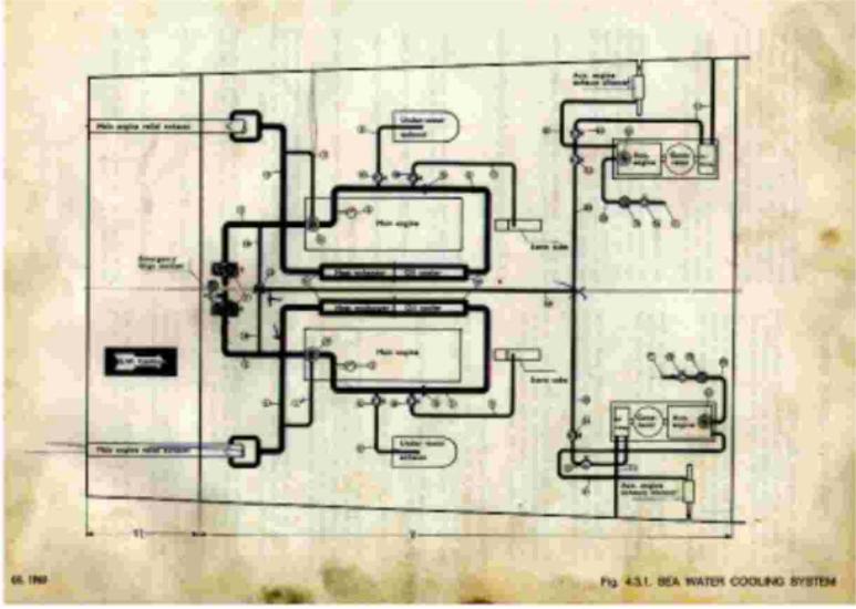
4.3.1.1. Description (fig. 4.3.1). The port and starboard sea water cooling systems are identical but independent of each other. Each system consists of main inlet valve with duplex strainer (1), engine driven centrifugal pump (29) and suitable pipes and valves for the various installation cooling demands.
Each system can be primed by cooling water from the auxiliary engines.
The Main Sea Water Inlet Valves (1) are placed in the oft part of section V, one on each side of the keel. Two strainers are fitted to each sea water inlet valve box. (See article 3.2.2.).
An emergency bilge suction is fitted to the starboard sea water inlet valve. (See article 4.7.2).
The Combined Oil Cooler and Heat Exchanger (30) and (31) is placed beneath the floorboards odjacent to the center line, and secured to the frames.
Priming and Venting. As the main engine sea water pumps (29) are not self- priming, the sea water cooling systems can be primed from the auxiliary engine sea water pumps. (See article 4.3.1.2.).
By opening valve (24) and change-over cock (27) water is directed to the selected engine sea water system, between the main inlet (non return) valve (1) and engine driven sea water pump (29). When the sea water sys- tem is filled and water is discharged overboard through a pipe (3) and the exhaust pipe, the main engine con be started and cock (27) can then be closed.
The engine driven centrifugal pumps (29) are fitted with running vents through pipes (7).
The Main Engine Cooling System. The engine driven pump (29) draws the water through inlet valve and strainer (1) and pipe (2), then pumps it through a restrictor plate (16) and pipe (3) through the oil cooler (30) and heat exchanger (31) and discharges it through pipe (3) into the exhaust pipe and overboard.
A pressure gauge (5) is fitted to the system.
Between the sea water pump and the restrictor plate (16) are outlets for cooling of:
The auxiliary engine sea water pump (32) draws the water from the inlet (17) through valve (18), strainer (19) and pipe (20) and then pumps is through the heat exchanger and pipe (21), through the exhaust pipe and discharges it overboard with the exhaust.
For cooling of the air compressor the water passes through valve (22) and pipes (23) and is discharged overboard at the boat side.
Valve (24) is for priming the main engine sea water systems (see article 4.3.1.1.).
The valves and pumps are made of bronze. Valve- housing and pipes are made of copper. For flexibility the pipe connections are mainly rubber hoses fastened with clips.
The sea water system pipelines are pressure tested to 1.75 kglcm2 -- 25 Lb./sq.in.
 |
Freshwater Cooling System |
 |
As shown in fig. 4.3.2. the fresh water cooling system to each engine installation is entirely independent of the other and only the storage tank is common to both.
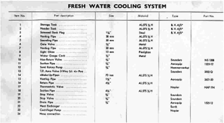
Each engine fresh water cooling system -- here in after celled coolant system -- is identical, consisting of header tank (2), heat exchanger (22), thermostatic valve (17) and suitable fittings and pipelines.
The Storage Tank (1) is placed below the floor- board oft of frame 43 in section IV. Mounted on rubber lined foundation between "A," and "B," girder and secured to the girders.
The Header Tank (2) is the highest point of the coolant system and is sited in a smell housing above deck level adjacent to the after engine room hatchway.
The Coolant Heat Exchanger (22) is part of the combined heat exchanger and oil cooler, as shown in the figure, which is secured to the frames beneath the floorboards adjacent ta the center line.
Filling, Venting and Draining. The storage tank is filled from the deck through pipe- line (3), and vented through gooseneck (4) above the floorboards in section IV.
On the top of the tank there is a screwed plug (5) to which a dipstick is fastened.
A drain valve (6) is fitted to the tank.
The header tank is filled from the storage tank by opening valve (19) and positioning change-over cock (13) to either port or starboard system, and then by the semi-rotary pump (12) the system is filled up to the maximum mark on the heeder tank sight glass (8).
During the initial filling operation, care must be token to vent the engine coolant system as detailed in "Deltic" Maintenance Manual,.
Should there be a loss of coolant during the running period, down to the minimum mark on the sight glass, the header tank can be "topped off" by the semi- rotary pump, but now venting is not necessary.
From the coolant junction box on "B," exhaust manifold a vent pipe (15) is led to an internal pipe in the header tank which discharges below the coolant level in the tank.
The tank is vented by internal pipe (7), the open end of which is in the bottom of the tank, in the engine room.
The engine coolant systems can be drained either by removing the drain plug in the bottom of the heat exchanger. Or if the coolant is to be re-used, by positioning the valves (19) and (20) and pumping out the coolant with the semi-rotary pump (12), through the hose connect piece (24) on the pressure side of the pump.
The final draining of the coolant residue in the engine should be carried out in accordance with instructions given in the "Deltic" Maintenance Manual,.
The Coolant Circulation. The coolant is circulated by the engine mounted centrifugal pump (23) through the engine, and from the outlet pipe (16) to the thermostatic valve (17), where the temperature is controlled, either by passage through the heat exchanger or the bypass to suction pipe (18) and pump (23).
The water in the header tank keeps the coolant system full through "Make-up-pipe" (14).
Storage tank. The storage tank is oil-welded of sea water resistant aluminum. It has two vertical bulkhead stiffeners.
Tank capacity: 270 liters -- 60 imp. Gals. -- 71 U.S. Gals.
The thank is pressure tested to 0.75 kglcm2 -- 10.7 Lb./sq.in.
Header tanks. The header tanks are all-welded of sea water resistant aluminum.
They are fitted with internal, perforated pipes connected to the vent pipes (15) from the engines. The outlets of these pipes are below the minimum mark of the tanks, to deaerate the water from the engines.
Each tank is also fitted with a sight glass (8) mounted on a valve (9) which is supplied with a cock for draining purposes.
Tank capacity: 35 liters each -- 7.7 imp. Gals -- 9.3 U.S. Gals.
The tanks are pressure tested to 0.5 kg/cm? -- 7 Lb./sq.in.
All the pipes for the fresh water cooling system are pressure tested to 1.75 kg/cm2 -- 25 Lb/sq.in.
 |
Fig 4.4 Air Starting System |
|
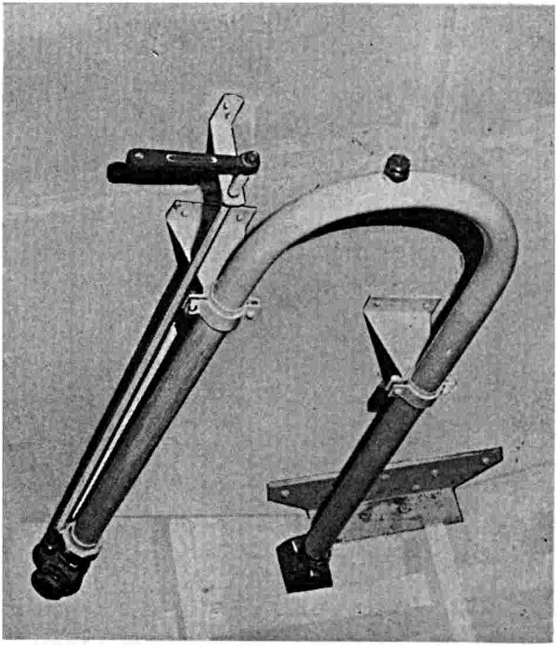
There are two identical air starting systems which con be cross connected. The systems consist of air compressors, air receivers and suitable high-pressure pipes and valves.
The air compressors are placed one on each generator set in the forward part of section V. The compressors are driven through clutch and belt-drive, which are mounted on on extended shaft from the auxiliary engine generators (see article 3.2.2.).
The air receivers (11) are placed in brackets on the bulkhead frame 49 near to the generator sets (see article 3.2.2.).
Filling and draining. The air receivers (11) ore filled from the compressors through pipes (1) and valves (2) to a working pressure of 30 kgicm2 -- 425 Lb/sq.in. and have a capacity of 56 liters -- 2 cu.ft. each. The safety valve (3) is adjusted to open at a pressure of 31.5 kglcm2 -- 447 Lb/sq.in.
The air receiver can be drained through a cock (7) and pipe (9) to the bilge. The cock (8) opens to the pressure gauge (10).
Air starting system. For starting the main engines, the air from the receiver is led through sop-valve (4) and pipes (5) to the hand starting valve (6). Both engines can be started from either or both air receivers by using the intermediate valve (12).
| Air compressor and receiver. |  |
Service tanks. The cylindrical service tanks are all-welded of seawater- resistant aluminum. The tanks are fitted out with internal de-aerators and connecting flanges for oil heaters.
Total capacity of each tank: 340 liters -- 75 imp. Gals - 90 U.S.
Gals.
Capacity to normal maximum operating level 240 liters -- 53 imp. Gals --
64 U.S. Gals.
Capacity to normal minimum operating level 136 liters -- 30 imp. Gals --
36 U.S. Gals.
The tanks are pressure tested to 0.75 kglcm2 -- 10.7 lb/sq.in.
All the pipes for the lubricating system ore pressure tested to 3.5 kglcm2 -- 50 Lb/sq.in.
All the exhaust pipes in the engine room except the outlet (5) ore covered with asbestos cloth lagging.
The 17 inch main exhaust pipe (1-2-3-4-6) leads the exhaust gases through the bottom of the hull through a square outlet (5) placed outboard of "C",-stringer in section V.
To cool the exhaust gases before they pass through the bottom of the hull, the main pipe (3) is fitted with on internal 1 inch. dia. spray pipe connected to the sea- water cooling system.
The 9 inch relief exhaust pipe (8) and the flexible pipe (7) branch from the main pipe (3), passes through the bulkhead between sections V and VI, through the aft compartment (section VI) and discharge overboard through the transom.
The pipe is flanged to the transom and bulkhead. The expansion is obtained by the rubber hose (9) and the flexible pipe (7).
To cool the exhaust gases the main engine cooling water is connected to the pipe and discharge overboard with the exhaust.
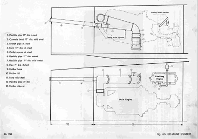 |
Fig 4.5 Exhaust System | 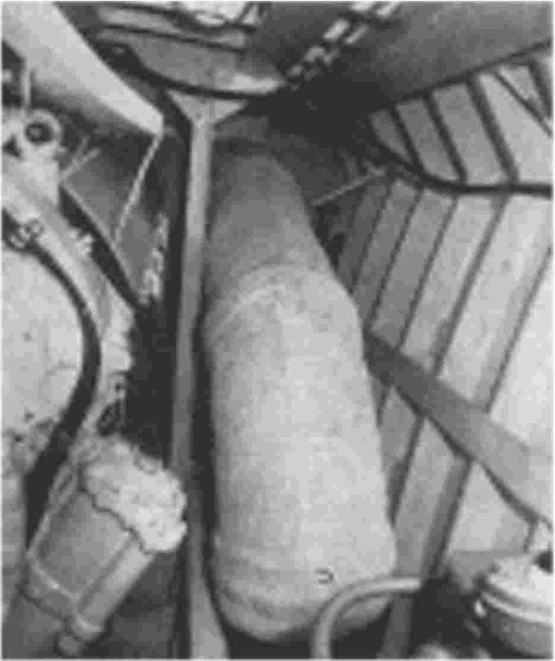 |
Main engine underwater exhaust outlet |
The exhaust system. For starting, slow running and running astern, the main port of the exhaust gases pass through the 9 inch relief pipe (8), as the exhaust back pressure in these circum- stances would be too high with underwater exhaust alone. As the speed of the boat increases most of the exhaust gases pass through the main underwater outlets.
When the engines not running rubber lids (10) are placed on the outlets at transom.
The auxiliary engine exhaust system consists of a steel pipe (11), a flexible pipe (12) and a rubber silencer (13).
The exhaust pipe and silencer are cooled by water injection into the exhaust. This water must be kept on when the engine is running, as the rubber silencer will not withstand high temperatures. The main engine underwater exhaust outlet.
Main engine air supply comes through a hood on the oft deck (1) a square plywood trunk (2) in the oft compartment, air splitter silencers (3) on the oft bulkhead, and ducts (4) into the engine blower inlets.
The hood (1) is fitted with a strainer-gauze. The air trunk (2) ends 90 cm (approx. 35 inches) above the floor- boards. Water entering the trunk (2) with the air drains off to the bilge, and only comparatively dry air enters the silencers (3) and the inlet ducts (4) to the engines.
For circulating the air in the engine room there is a hatch (9) in the bulkhead between sections V and VI. This hatch (9) when not in use and closed, is watertight.
Auxiliary Engine Air Supply. Normally the auxiliary engines take air from the engine room through hood (5) on deck and inlet (6) on the engine. There is also a cowl-type vent in the deck above each auxiliary engine.
| The air splitter silencer mounted on bulkhead |
|
 |
The hood on the oft deck |
| Fig 4.6 Air Supply | 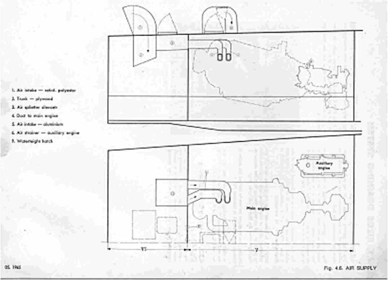 |
The bilge draining system is of the self boiling type, consisting of six bilge ejectors fitted to the bottom of the boot, alongside the keel.
Five of the ejectors are mounted in the oft port of watertight section Nos. 11, III, IV, V and VI. Each ejectors has a gate valve (1), operated by a lever mounted in an accessible position, on inverted U-pipe (2) fitted with a vent (3) and a strainer (4) at the inlet end.
The sixth ejector, mounted in the forward port of the engine room between frames 53 and 53'/2, is fitted with valve (1) and a suction pipe (5) to which a hose con be connected. engine a gate flexible
NOTE: It is important that the U-pipe vents (3) are maintained clear of obstructions, such as dirt or paint, to avoid the risk of water flowing from the ejector to the bilges when the boar is not under way.
Section I has no ejector but can be drained into section II through gate valve (6) in bulkhead No. 9.
In addition to the self boiling system large capacity deck mounted hand pumps (7), with strainers (8) are fitted in sections I, 11, III, IV, V and VI (See article 4.7.3.).
| (Fig. 4.7.) Drainage and Deckwash | 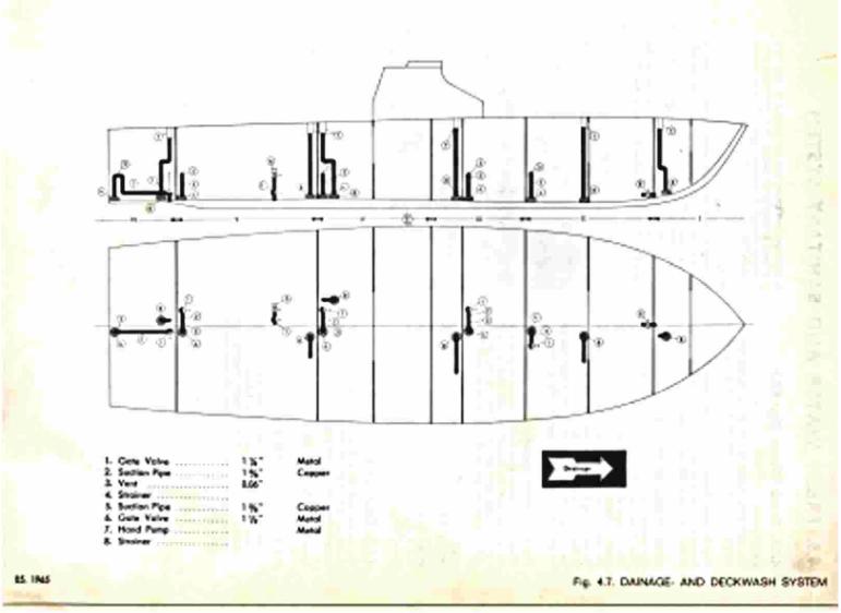 |
 |
A bilge ejector |
The starboard engine seawater emergency engine room bilge screw down non-return suction connected to the main engine Emergency Bilge Draining pump con be used as pump by opening the valve which is directly seawater inlet housing.
A hand bilge pump (7) is fitted in each watertight section. The hand bilge pumps (7) are placed under the upper deck and are operated from that deck. The pipes lead down to the bilge and are fitted with strainers (8).
| (Fig. 4.8.) Fresh Water and Sanitary | 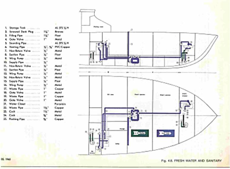 |
Description: The fresh water system consists of one storage tank (1), hand-pumps and associated valves and piping system.
The Storage Tank (1) is placed below the floor- boards in section II on the boat center line. It is fastened to the web frame and bottom frame.
Filling, Venting and Draining. The storage tank (1) is filled from deck through a screwed plug (2) and pipe (3) and is controlled by a valve (4). The sounding pipe (5) is fitted with a screwed plug to which a dipstick is welded. The storage tank is vented through a plastic vent pipe (6), the outlet being above the sink unit in the galley, in case of overflow when filling. The storage tank (1) is not fitted with a drain but can be emptied by the hand pumps (9), (13) or (16).
The Fresh Water System. Water for the crew's wash basin (section I) is taken from the storage tank (1) through the non-return valve (7) and associated hand pumping system (8) and (9). The delivery pipe (10) can be directed to either wash basin.
Water for the officers' wash basin is token from the storage tank through pipe (12) and hand pump (13). Water for the galley sink unit is taken from the storage tank through non-return valve (14), pipe (15) and hand- pump (16).
The storage tank (1) is of all-welded seawater-resistant aluminum, and fitted with internal bulkhead stiffeners. Capacity: 500 liters -- 110 imp Gals -- 132 U.S. Gals.
Pressure tested to 0.75 kgicm2 -- 10.7 Lb/sq.in.
All wash basins and sink unit drainage are discharged overboard below the water line as follows:
W. C. The boot is fitted with two water closets (21), one in the crew's lavatory (Section I), and one in the officers' lavatory (Section III). Discharge from W.C.'s go through pipes (22) and bottom valves (23) overboard.
The W.C.'s are flushed with seawater from valves (24) and pipes (25) with hand pumps mounted on the W.C.'s.
| The water closet in the crew's lavatory. | 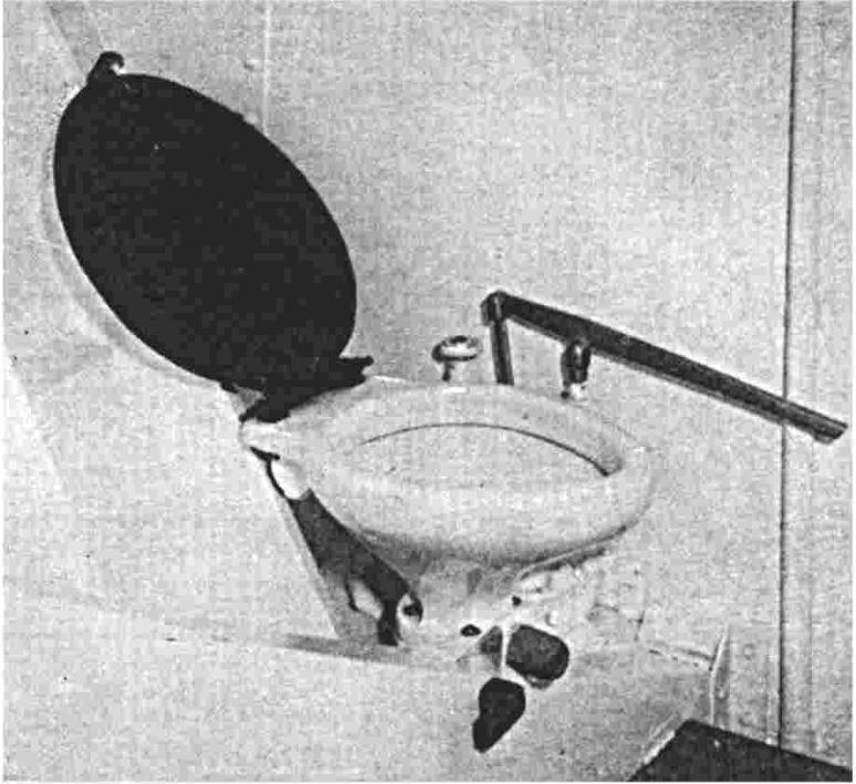 |
 |
Figure 4.9 Heating and Ventilation |
Description (fig. 4.9) The ventilation system consists of a thermotank (1) fitted with 3 heating elements, each having a capacity of 4 KW., on electrically driven centrifugal fan, an air filter and suitable switches, thermostats and ducts.
The thermotank (1) is situated on deck, in a compartment on the port side abaft the bridge. Aluminum ducts (7) lead from the thermotank fan housing through the deck into section IV and through sections III and II into section I, on both sides of the boat center line.
Adjustable valves (8) and (9) are fitted in the ducts for each compartment. An electrical control box is mounted in the plotting room. It is fitted with a maximum cut out switch and warning light for the electric fan (2), three switches (3) and warning lights for the three elements, and a phase inverter (4).
A fuse box (5) is also fitted (see illustration). A room thermostat (6) is placed on the aft bulkhead in section Il, port side.
| The electrical control box. | 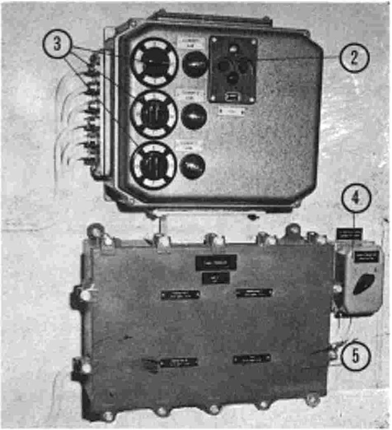 |
Adjustable valve (9), |
Ventilation. The ventilation system is operated from the electrical control box in the plotting room. For fresh air circulation only, the fan should be started.
If the air is to be heated, the heater switches (3) should be turned on. Each of the three switches operates an element of 4 KW capacity (Total 12 KW).
Should the heating elements become overheated due to too many duct outlets (8) and (9) being closed, on over- heating thermostat is fitted in the thermotank (1) which will automatically cut out the current supply to the elements.
A separate forced draft ventilation system is installed in each of the toilet rooms, the converter room and the galley. These compartments have deck vents (18) fitted with extractor fans as follows:
A switch marked "Fan converter room" is located in the plotting room.
In addition to the ventilation systems already described all compartments except section 1, are ventilated to the atmosphere through ventilators (15). These ventilators are of the cowl-type.
The natural draft ventilators con be closed manually from above and below the deck.
Ventilation of engine room, see article 4.6.
![]()