TECHNICAL |
Osprey Manual
|
|
|
[ Technical ] - 4 -
|
||||||||||||||||||||||||||||||||||||||||||||||||||||||||||||||||||||||||||||||||||||||||||||||||||||||||||||||||||
 |
 |
|
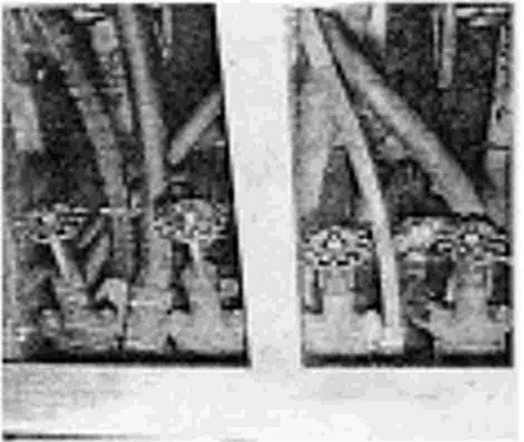
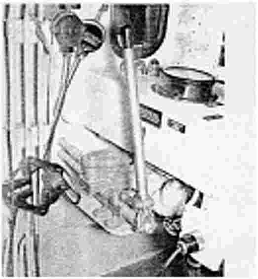
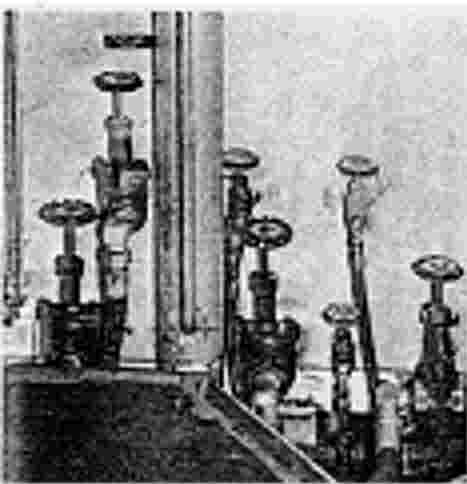
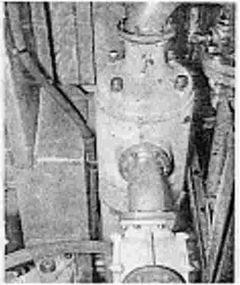
| Fig 4.1 Deck Vents | Fig 4.2 Supply Manifold |
(Actual sounding done by graduated dip stick), This method used only in place of nonfunctional gauges. The amount of fuel oil in day tank is read from a site glass on the fuel day tank (visible from engine control room). Note: Also vented and filled same method.
Filling, Venting, and Draining: The storage tanks are filled through deck fittings and filling pipes. The tank soundings can be made through this same fitting by a dip stick which is kept on frame (16) sixteen. Note: See Seacraft drawing attached in this section. The fuel oil is pumped from integral tanks to the manifold, from the manifold fuel is taken to the pump, and from the pump through a pair of fittings into the day tank.
This method keeps the day tank constantly supplied with fuel. From day tank the fuel is gravity fed to the engines. The unused fuel is then returned to the day tank.
 |
 |
 |
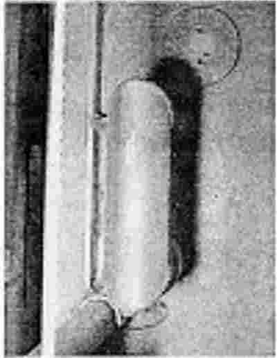
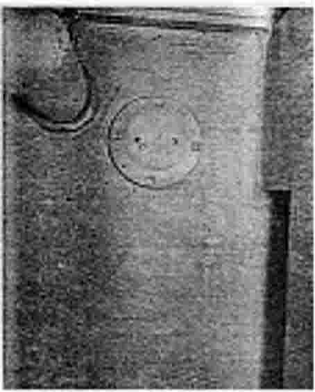
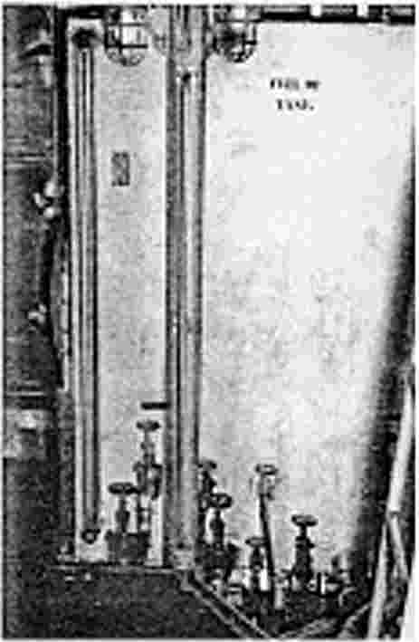
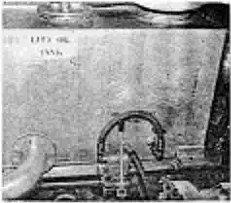
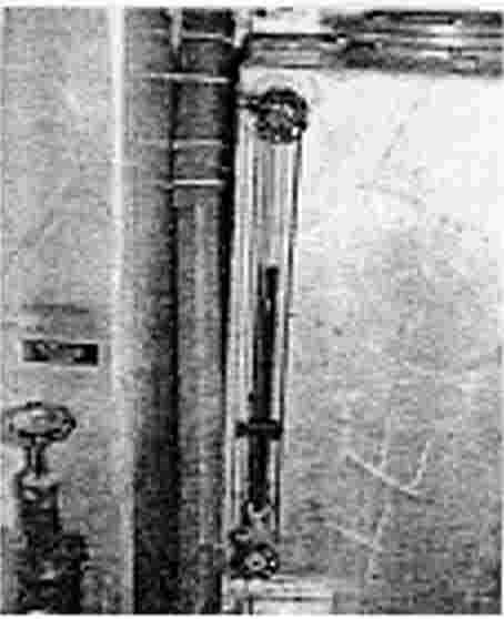
| Fig 4.3 Deck Fitting For Day Tank | Fig 4.4 Sight Glass For Day Tank | Fig 4.5 Main Engine Hand Priming Pump |
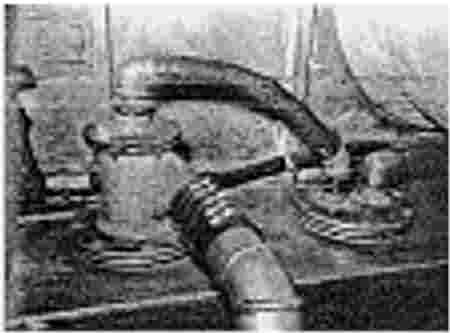
Main Engine Priming. The main engine fuel system must be primed before starting. This is accomplished by using hand priming pump and plug valves. The hand pump suction is taken from 1/2" supply pipe and discharged through plug valve and supply pipe line to a two stage valve on engine. If at any time, the fuel in day tank reaches the overflow position, the fuel will return to the return manifold where it is distributed to the selected integral fuel tank. Note: Fuel can be sent to either one of the tanks by closing valves.
Storage Tanks (1) The integral tanks are all welded of seawater resistant aluminum. They have horizontal and vertical internal bulkhead stiffeners. The standing material of 5456 Aluminum alloy. Note: Continuous welding on seams.
Tank Capacities CLASSIFIED
 |
 |
|
| Fig 4.7 Valve Layout on Day Tank |
Fig 4.6 Day Tank |
THE DAY TANK is welded of seawater resistant aluminum. The Day Tank is situated below the floorboard aft of bulkhead 27 and extending to bulkhead 31. This tank is mounted on neoprene gasket, devised for maximum shock absorbance. The tank is secured to aft bulk head 31 in the engine room with aluminum channels. Each service tank is identical and secured by brackets and girders on the floor bed. The tanks are situated on both port and starboard side of the boat.
Subject to correct positioning of 2-way valves on the tank, the service tank is then filled by the hand pump. (See figure 4.5 )
A drain valve is fitted to the tank. The service tank is vented from the tank by aeroquip hoses to lube oil deck vents mounted on extreme port and starboard side boat. Fixed deaerator oil filters in the system takes care of filtering all lube oil used in engine lubrication.
 |
 |
 |
| Fig 4.8 Service Tank Venting |
Fig 4.9 Heat Exchanger |
Fig 4.10 Oil Tanks |
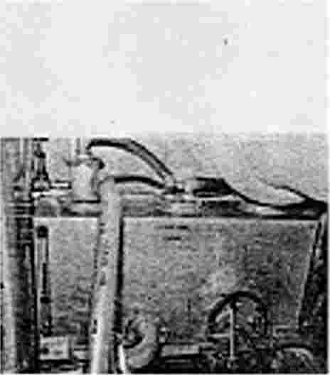
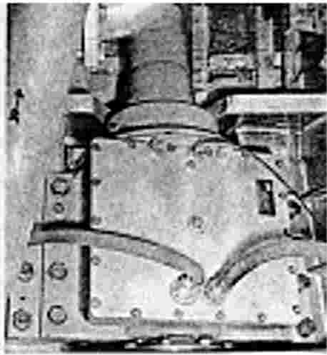
THE OIL COOLER is part of the combined heat exchanger which is secured to the frames beneath the floorboards adjacent to the center line. The temperature of the oil is lowered in the oil cooler by passing raw water through cooling tubes in the heat exchanger. The flow of water is determined by an engine driven pump. Prime the oil system before starting as described in Section VIII.
FILLING, VENTING , AND DRAINING The storage tank is filled through a deck fitting and a filling pipe, and is vented through a gooseneck above the floor board.
 |
 |
 |
| Fig 4.11 Hand Oil Priming Pump |
Fig 4.12Oil Level Sight Glass |
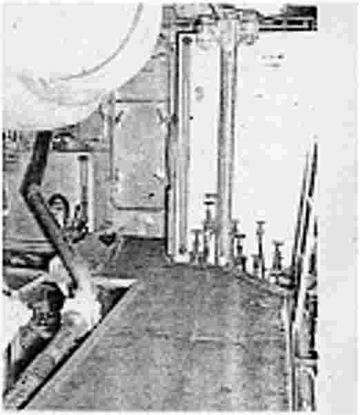
Fig 4.13 Engine Room Sight Window |
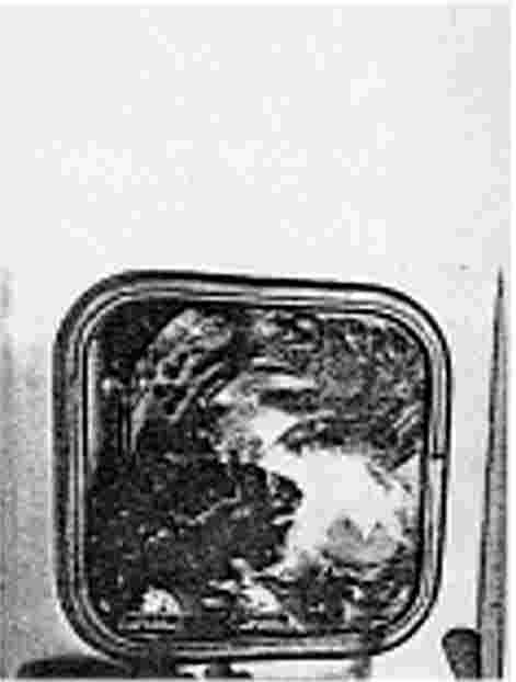
OIL LEVEL READING Each service lube oil tank is fitted with an oil level sight glass on which a maximum and minimum level is marked. The sight glass can be seen from control room area.
|
DISTRIBUTION OF COOLANT SYSTEM |
|||||||||||||||
|
 |
||||||||||||||
|
DISTRIBUTION OF EXTERNAL FUEL SYSTEM |
|||||||||||||||||||||||||||||||||||||||||||||
|
|
||||||||||||||||||||||||||||||||||||||||||||
Distribution of Lube Oil The lube oil is taken from a storage tank through the pressure oil pump (see fig. 4.27), then through adequate pipeline supply. Lube oil is evenly distributed throughout the engine to all functional pans.
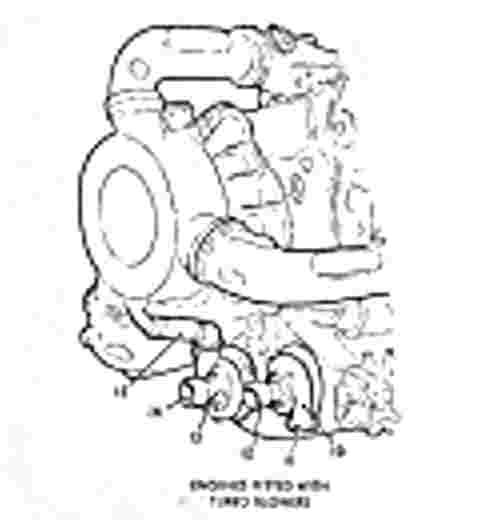
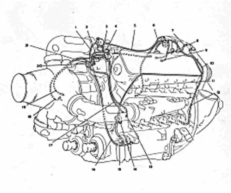
MAIN ENGINE LUBRICATING SYSTEM Each engine oil pressure pump (28) receives oil from the service tank through a valve and pipe lines. (See fig. 4.27). The main engine pressure filters (23) are integral with the Deltic engine.
 |
||
| Fig 4.14 De-aerator |
OIL IS RETURNED from the engine bottom crank case to service tank by the engine mounted scavenge oil pump(38). A thermo-static valve proportions the oil flow through a pipeline to the oil cooler and through the by-pass opening in the thermostatic valve, according to a predetermined temperature setting, and the oil is returned to the service tank through a de-aerator fitted on the deck.
Shown on (fig. 4.27), the lubricating system to each engine installation including the thrust blocks, is entirely independent of the other and only the storage tank, or day tank is common to both. Each engine lubricating system is identical (See fig. 4.27) for layout on type of method used. the system consists of service tank, oil cooler, thermostatic valves with suitable fittings and pipelines.
 |
 |
|
| Fig 4.15 Oil cooler |
Fig 4.16 Lube Oil Storage Tanks |
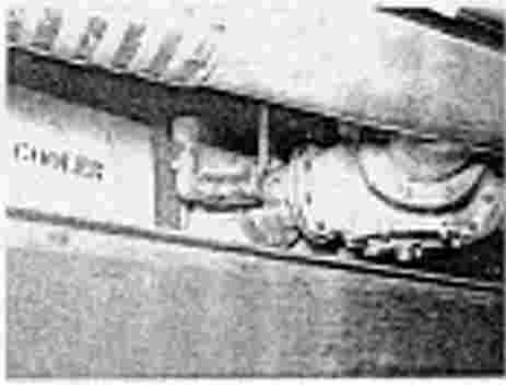
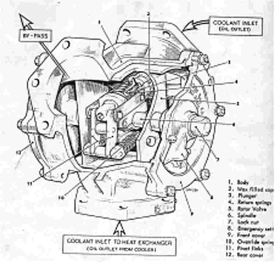
Thermostatic Valve (see fig. 4. 28). The thermostatic valve is operated in conjunction with the oil cooler. The temperature control is obtained through a wax filled capsule operating a rotary valve. This is fitted to the outlet from the oil cooler to obtain the required temperature at the engine inlet.
Thrust Blocks: Supply pipes, suitable to supply oil lubrication, to main engine thrust blocks are used in the same method of lubrication for main engine functional parts.
Service Tanks: The rectangular tanks are all welded of sea water resistant aluminum. The tanks are fitted with external de-aerators and connecting flanges for oil heaters. Total capacity for each tank: Approximately 130 gallons. All pipes for the lubricating system are pressure tested at 5 PSI.
The rectangular emergency storage tank is welded of seawater resistant aluminum. The tank is secure to the tank bed which is located on bulkhead 31 in the lazarette.
 |
 |
|
|
Fig 4.17 Thrust Block |
Fig 4.28 Thermostatic value |
![]()