TECHNICAL |
Osprey Manual
|
|
|
[ Technical ] - 3 -
|
 |
 |
|
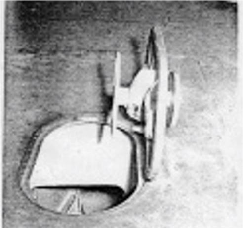
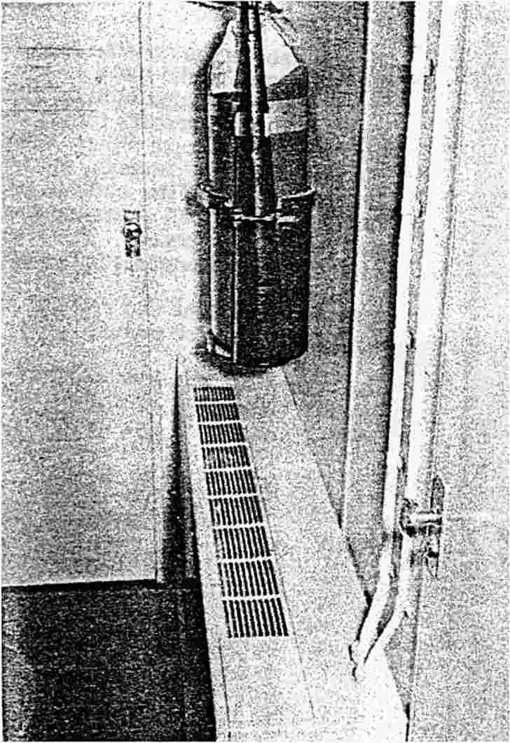
| Fig. 3.1 Watertight Deck Hatch | Fig. 3.2 Watertight Bridge Door |
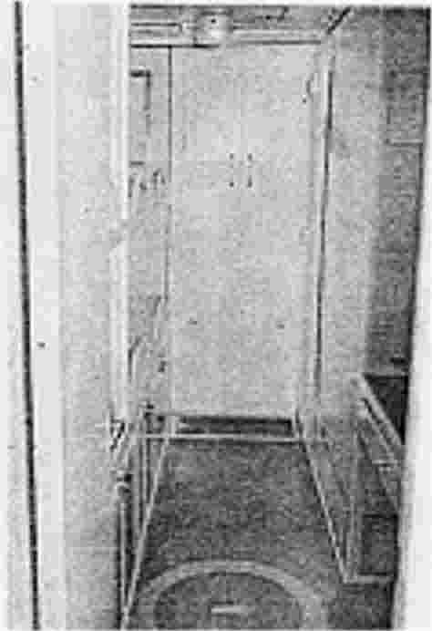
The Forecastle (Section I) located ahead of the first watertight bulkhead is used primarily as a crash compartment. Access to the forecastle is through a Baier hatch in the main deck.
 |
 |
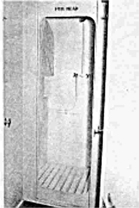 |
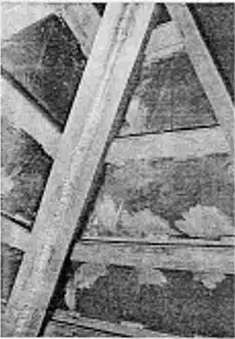
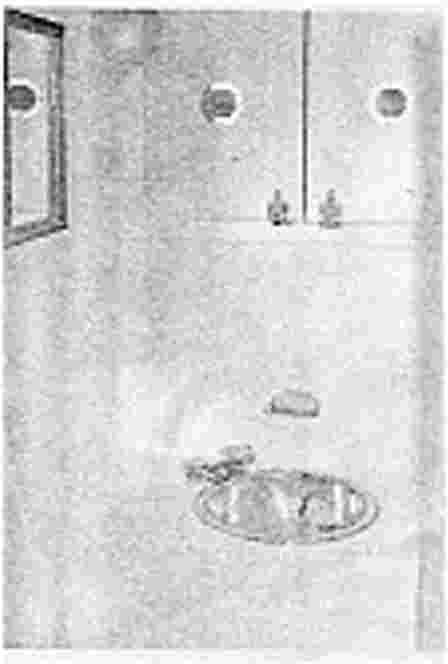
| Fig 3.3 Forecastle | Fig. 3.4 Sink | Fig. 3.5 Shower |
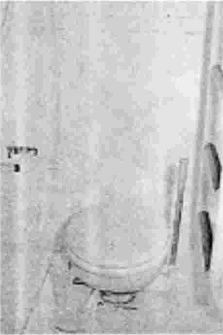
The Crew's Head (Section II, Fig. 3.4,3.5, and 3.6 ) is fitted with a pressure pump, sump pump, shower assembly, shower curtain, water closet, lavatory, mirror, soap dish, towel rack and locker space. Access is through the forward crew's quarters. A forward escape hatch is provided.
 |
 |
 |
| Fig 3.6 Crew Quarters Head | Fig 3.7 Crew Quarters (1) | Fig. 3.8 A/C Discharge Unit |
The Crew's Quarters (Section II) are divided into two parts - quarters (1) and quarters(2).
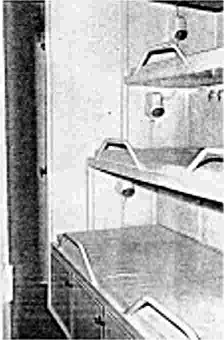
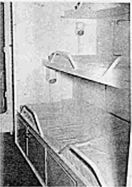
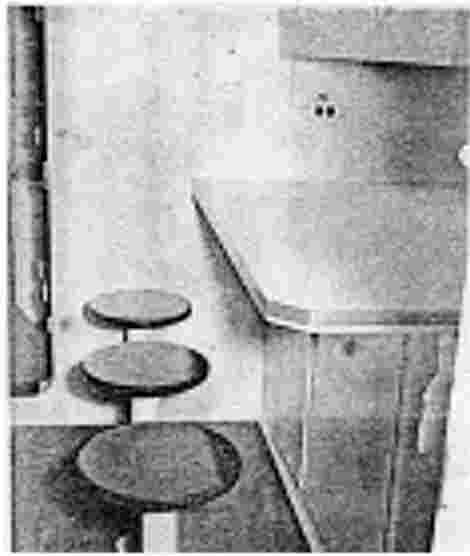
Crew's Quarters (2) (Section III) provides accommodations for six (6) men. There are three berths per side with one berth light and 6 cubic feet of locker space per berth. On center line at after bulkhead in quarters is a mess table with six (6) stools and over head lockers. The air conditioning discharge (3.8) is located between the two (2) crew quarters. All the berths are fitted with mattresses of four (4) inch foam rubber overlaid with canvas. Under the lower berths and at the ends between berths and bulkheads is locker space.
 |
 |
 |
| Fig 3.9 Crew Quarters (2) | Fig 3.10 Crew Quarters (2) | Fig. 3.11 Galley |
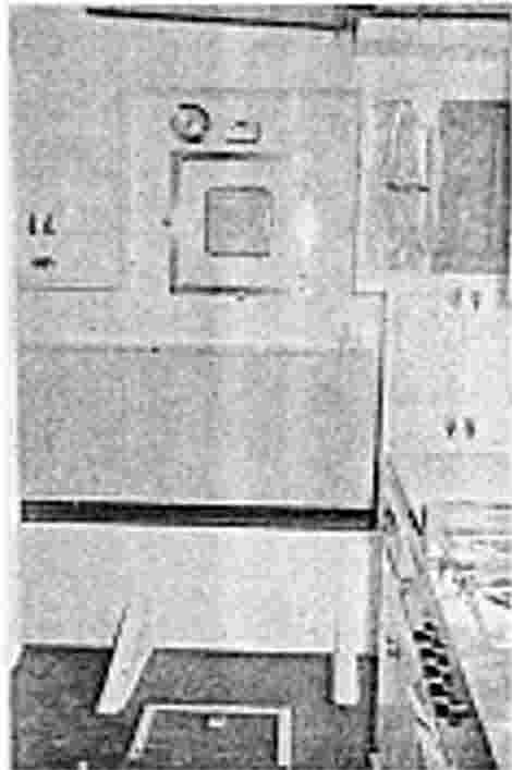
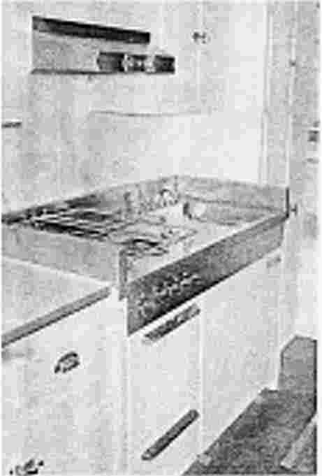
The Galley (Section IV) (Fig. 3.11) is located aft of crew's quarters (2) and is equipped as follows: The combination unit including sink, range and oven, is located against the aft bulkhead. A working shelf with lockers overhead and a port and starboard watertight door is located in the forward bulkhead. Three berths for sleeping accommodations with locker space are provided on the port side. The starboard side has locker space and an air conditioning discharge unit, and a hatch provides access to the structure.
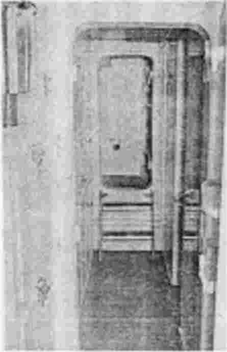
The Passage (Section V) connects the galley to the control center with access to the combat information center and officer's quarters. Storage and locker space is located on the starboard side. On the port side is the door leading to the officer's quarters and a ladder leading to the C.I.C. Located also on the port side is the small arms locker. On the aft bulkhead are the steps to the control room.
 |
 |
|
| Fig 3.12 Galley - Combination Unit | Fig 3.13 Passage |
The Officer's Quarters (Section V) is located port of the passage way through a joiner door. The officer's quarters is provided with four (4) berths on the aft bulkhead with one berth light and 6 cu. feet of locker space per berth. On the forward bulkhead is a built-in desk with locker space and chair.
The Officer's Head (Section V) is located on the port forward side of the compartment and is furnished as follows: Pressure pump, sump pump, shower assembly, shower curtains, water closet, lavatory, mirror, soap dish, towel rack and locker space.
 |
 |
 |
| Fig 3.14 Officer's Quarters | Fig 3.15 Officer's Head | Fig. 3.16 Control Room |
The Control Room (Section VI) is located aft of the passage way and officer's quarters entrance is through a watertight door from the passage way, or through a watertight door from the Engine Compartment. The control room is provided with all engine instrumentation and windows for viewing of the engine room. On the forward bulkhead is located the ammunition room and table space for the converters and the battery chargers. On the port side is the induction alternator storage, hot water heater and water pressure system. On the starboard side is the air conditioning unit. All pertinent information is available in the manufacturers manual supplied on board. Also on the starboard side is locker and storage space.
 |
 |
|
| Fig 3.17 C.I.C. | Fig 3.17 C.I.C. | Fig 3.18 Engine Room |
The Combat Information Center located directly above the officer's quarters has access from the flying bridge through a watertight door or by a ladder to the passage below deck. Housed in the Combat Information Center is navigation and communication equipment. Seats are provided for two (2) men located for easy operation of equipment.
The Engine Room (Section VII), as described in article 3.2.2., is located directly behind the control room. The twin screw propulsion installation consists of two (2) shaft lines utilizing Napier - Deltic diesel propulsion systems with a reverse reduction gear.
 |
 |
|
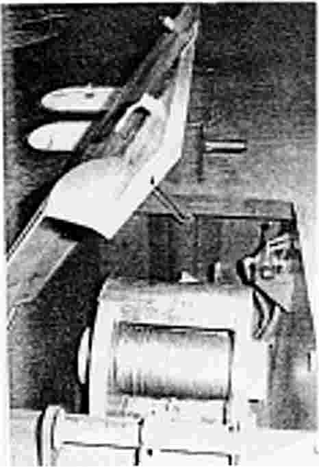
| Fig 3.19 Auxiliary Room | Fig 3.20 Vee Drive |
Twin thrust blocks are coupled to the engines to relieve high engine torque on the shafts. The intricate piping systems and wiring systems can be found in Article 3.2. in this manual.
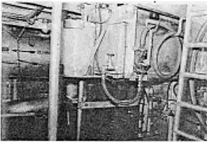
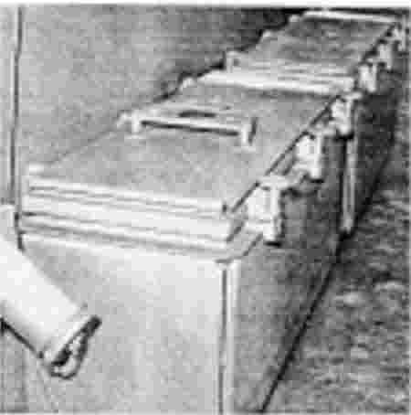
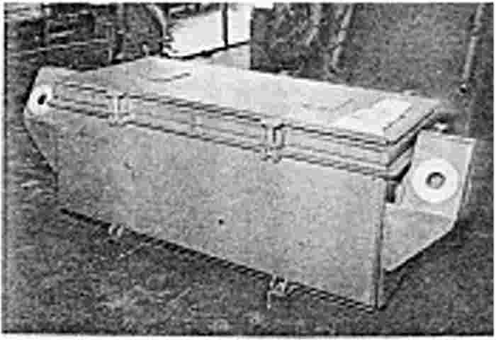
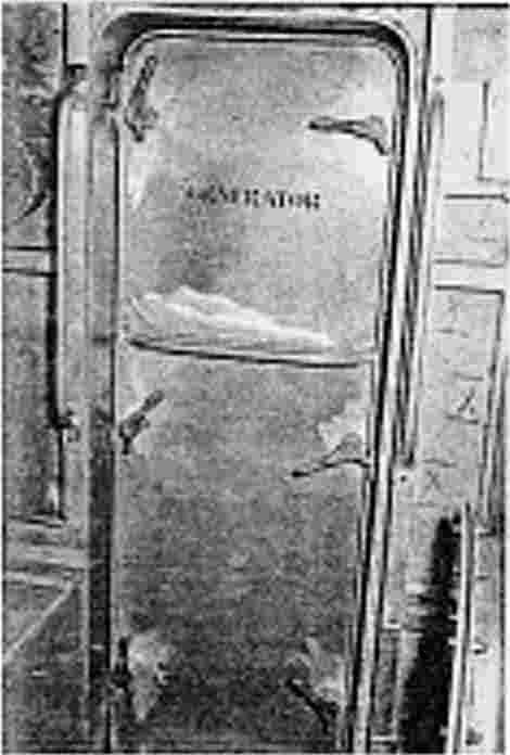
The Auxiliary Machinery Compartment (Section VIII) houses two (2) 30 KW Delco Generators powered by Detroit Diesel engines for the ship's power source. The main engine silencers are located port and starboard. Two banks of batteries are supplied for the generator starting system.
 |
||
| Fig. 3.21 Lazarette |
The Lazarette (Section IX) houses one fresh water tank on the port side and one on the starboard side. Coupled to the fresh water tanks is an A.M.F. water evaporator with chlorinator. All technical information can be found in the manufacturers manual supplied on board. The steering gear as described in Article 3.3.2. is also located in the lazarette and the attachments for emergency steering are provided.
Storage areas below deck are described in Article 3.1.2. Storage areas on deck are as follows: Four (4) Ready Boxes, providing space for 32 magazines (8 per box) or 1920 rounds, 2 port and 2 starboard are located beside the superstructure for the 20 MM guns. One ready box (on the forward deck is pro- vided for the dl MM mortar) providing space for 2 cases or 24 rounds.
 |
 |
|
| Fig. 3.22 20MM Ready Boxes | Fig 3.24 81MM Mortar Ready Box |
Two (2) Ready Boxes, 1 port and 1 starboard, are provided on the aft deck for the 40 MM gun. Each box contains 8 cases or 128 rounds, total 16 cases or 256 rounds. Gun barrel storage is provided on deck beside the Flying Bridge port and starboard. In the space described in Section 3.1.2. be low decks is storage for the following:
40 MM Gun - 36 cases or 576 rounds
Small Arms 1 - case
81 MM Gun - 48 rounds
For the removal of the larger equipment, which is too big to pass through the water- tight hatches, removable deck sections are provided.
 |
||
| Fig 3.23 Removable Deck Section |
The boat machinery is placed in two compartments (Section VII, Section VIII). The main propulsion engine, thrust blocks, day tank and oil tanks are located in the engine compartment (Section VII.)
The main engine controls are located in the control. room (Section VI.) Sections VII and VIII are divided by a watertight bulkhead fitted with a watertight door. Inspection windows are provided over the control desk to give an easy view of the machinery.
 |
 |
 |
| Fig. 3.26 Watertight door | Fig. 3.27 Remote Controls | Fig. 3.25 Main Engine Controls |
The main engines are operated from the control room or from the flying bridge by remote controls. It is not necessary to keep a permanent watch in the engine room, provided periodical inspections are carried out. All tanks that are located in the engine room are situated in-such a manner that they are easily accessible and away from any hot exhaust or other unsuitable surroundings. Rubber hose connections and Aeroquip flexible lines are used throughout the installation to resist vibration. All piping, wiring and control systems passing through the bulkheads are made watertight. More detailed descriptions for the main and auxiliary engines are given in section IV.
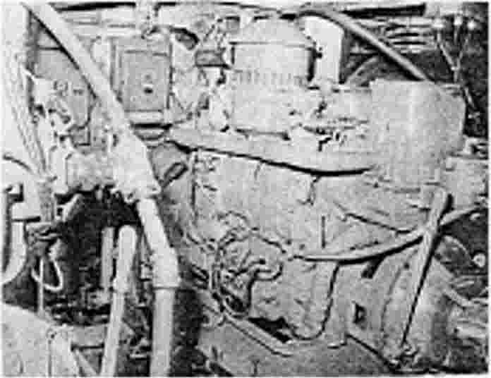
The main engines are installed port and starboard of center line with the output coupling facing aft. Power is transmitted from the engine to the thrust block and then to the propeller shaft. The Deltic engines are manufactured by D, Napier & Son Ltd., England. The type T28-37 is a 18 cylinder, straight forward, high speed, two stroke, uniflow engine that is pressure charged and liquid cooled. The rated output at 2100 rpm is 3100 b.h.p. The engine is fitted with a bi-directional gearbox with a ratio of 1.8574:1 both clockwise and counter clock- wise. The Deltic engines acquire the name from the inverted delta or triangular configuration of the cylinders, each cylinder block forming a side of an equilateral triangle with a crankcase at each corner. As the engine is an opposed-piston type, this arrangement enables each crankshaft to adjacent cylinders, two connecting rods being attached to each crank throw.
 |
 |
 |
| Fig 3.28 After Engine Room | Fig. 3.29 Deltic Engine | Fig. 3.30 Air Compressors |
Phase gearings at the driving end links the three (3) crank shafts, and combines the outputs in a common drive to the hydraulically operated forward and reverse clutch, and the reduction gear output coupling. The two (2) engines are similar and to obtain opposite rotations of the propeller, oil pipes for the hydraulic clutch merely to be cross connected on one of the engines. Any engine can then be used in the port or starboard position. For further engine details see "Deltic Maintenance Manual" publication 505 supplied on board.
THE THRUST BLOCKS supplied by D. Napier & Son Ltd. are supplied with thrust pads and are mounted for left and right hand installation. It is important that the correct hand of thrust pads are used. For further details see "Michell Thrust Blocks Operation and Maintenance Manual."
THE CARDAN SHAFT'S are connected to the engine flanges and the thrust block input flanges. The shaft is fitted with two sets of gear couplings. The clearances between the gear teeth are such as to allow for some movement between engine and thrust block due to the flexible mounting of the engines.
THE COMPRESSORS are mounted on foundations built on the starboard side of the engine compartment above the engine room walk level. There are two (2) Ingersol-Rand, mode1 231x 2 air compressors with 450 psi capacity used. The air compressor feeds two (2) certified 3 cu. ft. tanks also placed on the starboard side of the engine room. From the air compressors the air is fed to the control panel, through the main engine starting controls in the control room, and back to the engines. All penetrations through any watertight bulkhead are installed watertight. For further information on the air compressors refer to the "Ingersoll-Rand Maintenance Manual."
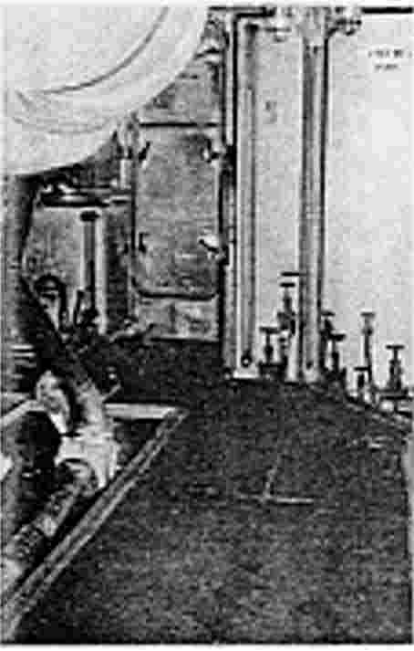
The oil coolers and heat exchangers are installed on foundations fastened to the bottom frames one on each side of the boat center line below the floor- boards. The oil coolers and heat exchangers are manufactured by Serck Radiators Ltd, They are two separate units and are bolted together, making a single unit. They are constructed of cylinders having both inlet and outlet connections for the oil and coolant and have end caps fitted to enclose the tube stacks. The seawater flows through tube stacks that are built up from many smaller tubes. The sea water is pumped by engine driven pumps to the heat exchanger through the silencers, resonators and overboard. Thermostatic valves regulate the temperatures of the coolant and oil. Two (2) lube oil tanks are located in the engine compartment and a description can be found in section 4 of this manual. Found in the engine compartment are 00-2 system outlets as described in section 6. For all piping and systems descriptions in the engine compartment refer to Section 4
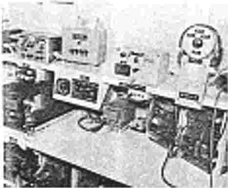
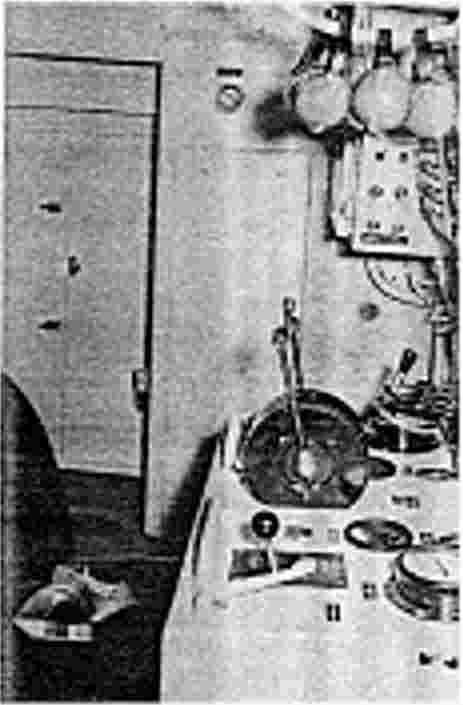
The control room is described in article 3.1.2. A further description of the equipment in the control room is given below. The main switch board and control panel for electrical distribution is described in Section 5. The instrument panels for port and starboard main engines are found in the control room console and on the flying bridge, layout and description is given in Section 5. Housed on the port side of the control room is the water pressure system, the hot water heater and the inductor alternator all placed in a separate section closed from the main control section. Directly behind the central panel forward is located a small room for the converters, battery chargers and battery storage. On the starboard side of the control room is the air conditioning compressor and entrance to the passage.
 |
 |
|
| Fig 3.31 Control Room | Fig 3.32 Console Layout |
The main engine control desk is placed against the aft bulkhead of the control room and is filled with the following:
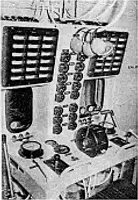
Directly in the center of the console is the main engine control levers for forward or astern; directly port and starboard are the running levers, and just outboard are the engine start levers situated port and starboard of the main control levers. In the center of the console is located the clutch delay isolating switches one for each clutch. Directly above are the tachometers. Above the tachometers are the fuel rack indicators. On the outboard sides of the Indicator are the air pressure gauges.
Located at the top of the console are two sets of instrumentation (port and starboard) which include the low oil pressure light, the water temperature light and the clutch delay light. Directly above the console located in between the two engine sight windows is a double row of instruments which include from bottom to top: the oil temperature thrust block meters, the oil temperature "out" meters, the oil temperature in" meters, the coolant temperature meters, the coolant pressure meters, the engine oil pressure meters and the fuel pressure meters. The two rows are identical and designated port and starboard. Directly above the two rows of meters is the hydraulic pressure meter. Directly port and starboard are also two (2) panels employing 18 engine monitoring meters.
 |
 |
 |
| Fig. 3.33 Converter Room | Fig.3.34 Control Room |
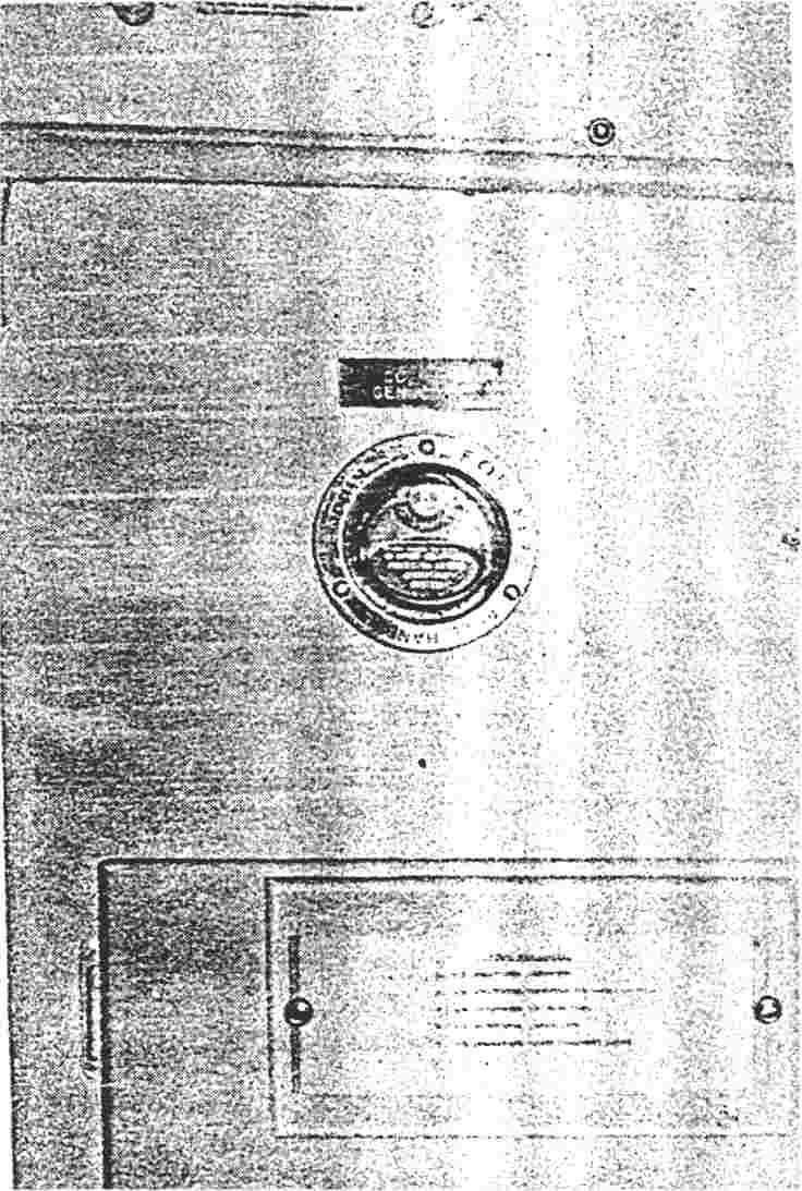
Fig.3.35 CO2 Pull Station |
Through the sight windows four (4) gauges are visible. They are: the starboard sea water pump discharge, the starboard bilge pump discharge, the port bilge pump discharge and the port sea water pump discharge. Directly on the starboard side of the console is the day tank fuel pump switch. Located on the side of the main control panel facing the console is the auxiliary engine starting switches, and the oil pressure and water temperature lights. Located at the sides of the console port and starboard are the air valves for starting. Located directly above the door to the engine compartment is the evaporator sea water pump switch and on the port side of the evaporator switch is the evaporator fresh water pump switch. Directly port of the evaporate switch is the aqua-purometer and the main switch. Directly to the port side of the watertight door to the engine compartment is locate electrical panel which is described in Section "5" Immediately beside the door to the hot water heater is located the CO-2 pull for engine room. On the forward wall of the control room is located the air circulation blower switch and the air conditioning and heating controls. Directly beside the door to the passage way is located electrical panel "4' and on the starboard wall is electrical panel "3". These panels are described in Section "5".
The main and auxiliary engines are fitted with a mechanical type remote control to the control room. The control system is designed to permit operation of the engines from either the control room or the bridge. The function of gear changing and speed selection is carried out by a lever from either the control room or the bridge. The levers are connected in tandem through a single cable and function box to both the hydraulic governor and the hydraulic control unit. This arrangement permits the automatic selection of the correct engine speed during gear changing and the retention of the required gear during subsequent speed changes. For further information see "Deltic Maintenance Manual", publication 501. Main engine shut-down is accomplished by a hand operated shut down lever situated in the control room beside the speed control lever. When the lever is moved to "STOP" the shut- down cable moves the governor shut-down lever and shut-down probe lever, which in turn depresses the servo valve to stop the engine.
 |
||
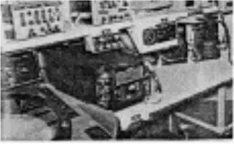
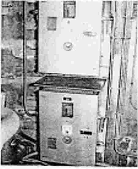
| Fig 3.36 Battery Converters |
Auxiliary Engines Speed Control
The auxiliary engines remote speed controls are mainly fitted to adjust the voltage and frequency on the generators. The control-knobs, one for each engine, are situated on the port side of the main distribution panel in the control room. For a description of the auxiliary controls refer to 3.2.3 in this section. The steering arrangement consists of three main components:
Rudders with rudder- stops, bushing and stuffing boxes.
Steering equipment.
Emergency steering
1. Rudders: The boat is fitted with two rudders designed and manufactured by Sewart Sea- craft.
The boat is fitted with eight mooring cleats, two forward, two mid ship two aft and two on the transom. The mooring cleats are welded to the chine, also provided is one heavy riding bitt placed behind the anchor windlass well.
A bow chock is mounted on the stem to lead the anchoring cables. Two 200# Stockless anchors are provided one of which is fastened to 600 feet of 1/2' Stainless Steel cable and 2 fathoms of 3/8" Galvanized chain, on the hydraulic anchor windlass and stored in the bow chock on the stem. The second anchor is placed on deck in the anchor chock provided. The boat is also equipped with two 80' x 1/2" mooring lines and one boat hook.
 |
||
| Fig. 3.37 Hydraulic Anchor Windlass |
The boat is equipped with two 10 man automatically inflatable rubber life floats, manufactured by R.F.D. Incorporated. When the hook fastening the float to the cradle is re- leased and the float throw overboard, it will automatically release the mechanism to inflate the float with C02 gas, which is stored in a bottle with the unit. Nineteen lifejackets are provided and stored in lockers on the starboard side of the passage way. Because of the speed and maneuverability of these boats, they are very quick in movements, and care should be taken when moving around on deck.
The miscellaneous deck fittings found on this boat are listed below:
Hatches for access to the compartments below deck.
Emergency steering.
Vents for the fuel tanks.
Air inlet to the main engines.
Hatch and air inlet to the engine room.
Expansion tanks for the main engine cooling system.
Vents for venting the compartments below deck.
Filling pipes for storage tanks.
Handrails
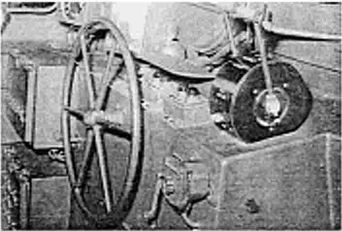
The superstructure amid ship is a combination of open bridge and Combat Information Center. It is constructed of aluminum and has aluminum port light covers for the C. I. C. port lights. On the aft end of the bridge is an aluminum main engine vent trunk and on top is the radar mast, deck lights, and yard arm mast. The Flying bridge is fitted with a Plexiglas windshield incorporating 8 windows, giving maximum visibility. Access to the flying bridge is from the port or starboard side of the engine vent trunk or through the watertight door to the C.I.C.
The following equipment is mounted on the flying bridge:
Rudder angle indicator mounted on the port side of the console arrangement.
Depth indicator mounted on the port side of the console arrangement.
Gyro mounted directly behind the steering wheel.
Main engine safety alarms mounted to the starboard side of the console arrangement.
Tachometers mounted directly behind the safety alarms.
Engine controls mounted to the starboard side of the console.
ARC-27 remote -control mounted to the windshield on the starboard side.
Air horn lever mounted on the front of the console.
Remote Radio hand set for the ARC-94 mounted on the front of the console.
Remote Radio hand set for the ARC-27 mounted on the front of the console.
Panel no. 6 mounted on the front of the console.
Panel no. 5 mounted on the front of the console.
General alarm switch mounted on the port side of the bridge.
Cease fire alarm switch mounted port side of the bridge.
Navigation phone switch mounted port side of the bridge.
Two Carlisle & Finch signal blinkers mounted port and starboard on the bridge railing.
Standard Merchant binnacle mounted behind the Helmsman's chair.
Two chairs (Officer's chair & Helms man's chair)
Signal Key mounted on the front of the main engine vent trunk.
Loud speaker on the aft side of flying bridge.
Radar disabling switch on front of the main engine vent trunk.
The hull, decks, superstructure, and all interior surfaces that are painted are first coated with a primer coat to a thickness of four mils.
The exterior hull from keel, including fixed appendages to the painted water line are painted as specified below to a minimum total dry film thickness of 10 plus 1 mils.
When the boat is delivered from the yard it is painted as specified, however the painted surfaces have to be maintained. The maintenance should be carried out before the paint is worn through. It is very important that the surfaces to be painted are clean and dry, as the paint is water resistant and will not penetrate the wet surface. Old loose paint, grease, and oil should be scraped off and the surfaces washed and thoroughly dried before new paint is added. Where the paint has been worn off priming paint in accordance with the specification should be used.
![]()