TECHNICAL |
Deltic Design
|
|
|
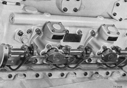
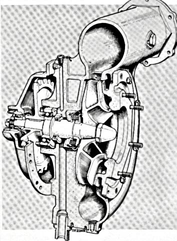
[ Technical ] SCAVENGE AIR BLOWERA single-stage centrifugal blower, mounted on the free end of the engine and driven through flexible shafts from the crankshaft gears, provides an air flow that completely scavenges the combustion chambers and provides a degree of supercharge. The blower and its driving gears form and independent unit that can be readily interchanged. INJECTION SYSTEM
The pumps for each cylinder block are supplied with fuel from a common pressurized fuel line in a circulation system which precludes air locks. The design permits any one pump to be removed and replaced by another, correct timing and matching being automatically obtained LUBRICATION SYSTEM
The single pressure pump supplies all services, including the metering pumps which control the flow to the blower bearings and to the sparge jets which spray the meshing points of the various gears. Oil is taken from the crankshafts, through ducts in the connecting rods and gudgeon pin housings, to cool the pistons and is then discharged through drain holes to the crankcase. EXHAUST SYSTEMA water-cooled exhaust manifold is fitted to each cylinder block and all three manifolds are normally coupled to a common expansion tank, but other suitable agreed arrangements may be adopted. The temperature of the gas flow from each cylinder is measured by individual thermocouples fitted in the manifolds. ENGINE COOLINGCooling is effected mainly by a fresh water circulating system, but the heat transfer properties of the lubricating oil are also utilized.
CONTROLSThe fuel injection system (and the ahead-and-astern gearbox, when fitted) is controlled automatically by movement of a single lever; except for starting and stopping, when the engine is controlled by a second lever that overrides the automatic system. - AHEAD AND ASTERN GEARBOXThe ahead-and-astern gearbox incorporates a hydraulically-operated friction clutch, which enables the engine to idle in neutral, or to drive ahead or astern through spur gears in constant mesh simultaneous selection of the required drive and the desired speed is made with a single control lever that moves over a quadrant from a central 'Neutral' position to 'AHEAD" in one direction, or to 'ASTERN' in the other direction. The control system switches the clutch operating oil to the appropriate side of the hydraulic clutch in the gearbox and compresses the desired speed upon the hydraulic governor which relays it to the fuel controls after it has made allowance for engine load and running conditions. The gear trains are lubricated and cooled by oil delivered through sparge jets from the engine lubrication system, and from an auxiliary pump that continues to supply oil when the engine is stopped if the gears are rotated by the propeller trailing. Provision is made for starting an engine by running on another and 'trailing in'. ENGINE MOUNTINGThe light weight and balanced thrust of the Deltic enables flexible mountings to be employed for carrying the engine, thereby completely isolating the bearers or structure from pulsations and accommodating thermal expansion. EXTERNAL FINISHThe external surfaces of all castings are finished in enamel and all other parts liable to corrosion are cadmium or tin-plated. All circulating pipes are marked with colored bands to enable the various systems to be readily identified, and servicing points are clearly marked. |